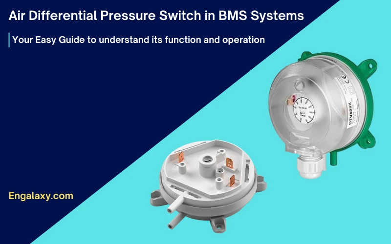
What is a differential pressure switch?
A Differential pressure switch, differential pressure switches, or air differential pressure switch, commonly called DPS, it’s an advanced device that triggers an electric switch based on the differential pressure detected between two points.
The differential pressure switch can be used for air or water systems, but each is a separate device.
We use this device to be connected with the Building Management System, or BMS System.

But in this blog post, we will cover the DPS that is being used with the air systems.
In DPS for Air, the electric switch is subsequently utilized to gauge the airflow status across fans and identify the level of dirtiness across the filters in the air handling unit or the airflow status of air handling systems.
Additionally, it can connect with any control circuit to execute the necessary operations when the switch turns on or off.
This state-of-the-art technology is crucial in ensuring efficient performance across various industrial applications.
What are the components of DPS?
To better understand how differential pressure switch works with air systems, let us know the components and information available on a DPS.
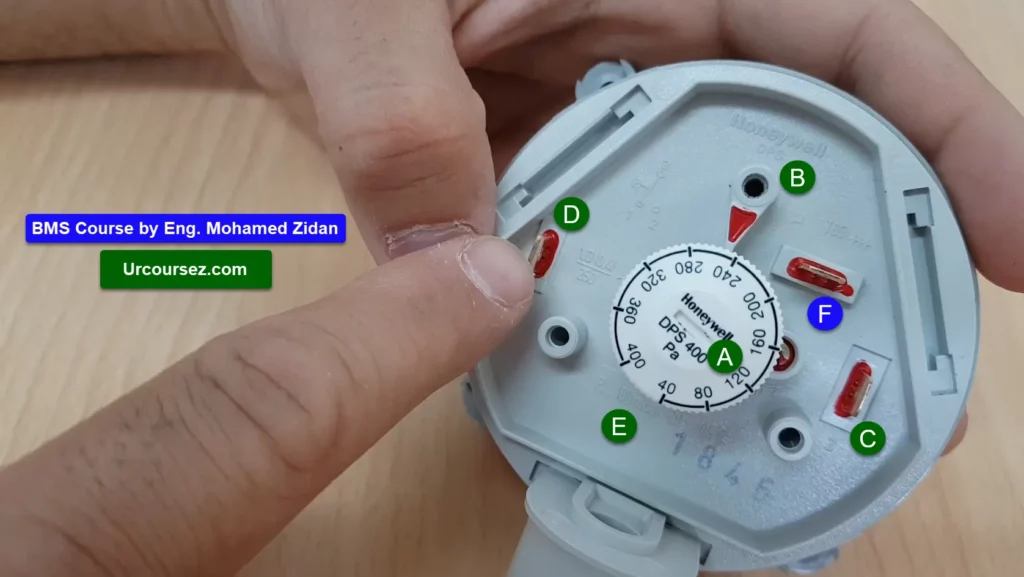
As you can see in this photo, the DPS consists of different items as follows:
Operating Range
It’s the range of variances in differential pressures or flow rates which can be calibrated for the activation of an electric switch by a specific sensing mechanism.
As you can see in photo number 2, item number A is the operating range of this DPS, which can read a difference in the pressure from 40 to 400 Pa.
Setpoint
The precise threshold of air pressure or flow rate that triggers the activation of the electric switch
As you can see in photo number 2, item number B is the pointer at the set point of the range.
Normally Open Switch
A switch known as the “Normally Open Switch” features contacts that remain in an open state by default. Upon actuation, these contacts are brought together to establish a closed state.
As you can see in photo number 2, item number C is the pin of the normally open terminal.
Normally Closed Switch
A switch usually possesses closed contacts, which are in a state of closure by default. The operation of the switch causes the contacts to open up.
As you can see in photo number 2, item number D is the pin of the normally closed terminal.
Common Point
We will use this point to close the path of the normally closed point or normally open point.
As you can see in photo number 2, item number E shows the pin of the common terminal.
Operating Conditions:
As you can see in photo number 2, item number F shows the details of the operating conditions of this DPS.
Where the maximum pressure (Pmax) is 100mbar.
The medium ambient temperatures are -20 to 85 celsius.
Examples of using the DPS
Example 1:
We can use this DPS on filters like pre-filter or bag filters of an Air handling unit or AHU.
This is to monitor the status of the dirtiness of the filters and to send an alarm to the operator in the control room.
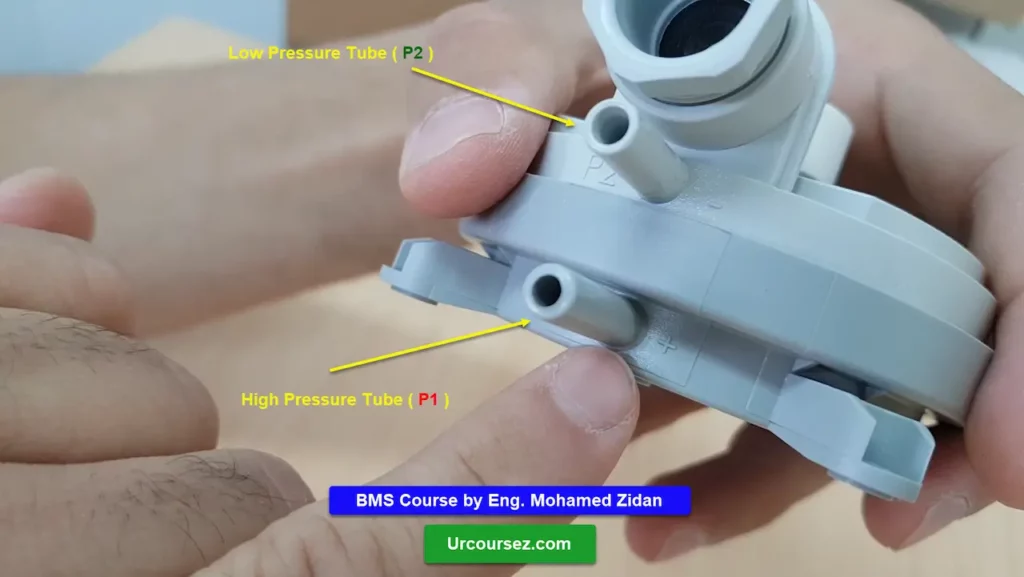
As we know, the pressure before the filter is higher than the pressure after the filter, so as you can see in these two photos, 3 & 4, we install the high-pressure tube before the filter and install the low-pressure tube after the filter.
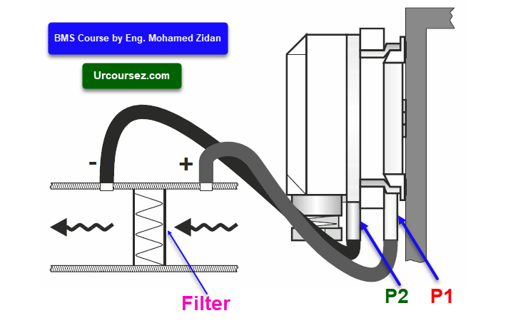
So, in the normal condition, we will have a value (pre-set value) for the difference in pressure between the pressures before and after the filter.
We need to send an alarm to the maintenance team when the filters are dirty, and this happens when the difference between the two pressures exceeds the pre-set value.
That’s why it comes to the importance of the DPS in this case, as it will change the status of its contacts from open to close, which will send an alarm signal to the operator that the filter is dirty.
As you can see in this photo 5, we installed a DPS on the pre & final filters of an AHU, the wires are connected at terminals 2 & 3, which is the normally open condition, and the set point is 120 Pa, so when the value of the pressure difference exceeds 120 Pa, so the switch will be changed from open to close status.
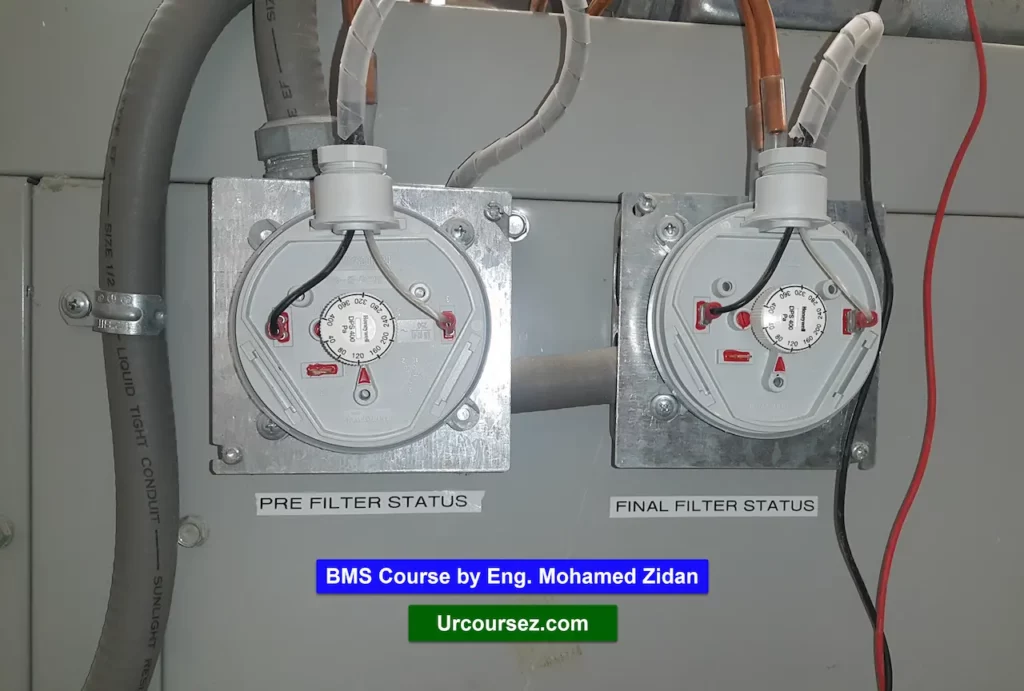
And so this signal can be sent to a controller to send a signal to the operator of the BMS system that the filter of this AHU is dirty and needs to be cleaned to allow the smooth operation of the AHU.
Remark:
By the way, if you would like to know more about the sequence of operation of AHU, we recommend you to have a look at our blog post about this topic from this link:
Example 2:
Also, we can install this DPS on the fan’s motor, like the supply or return fans of the AHU.
This is to monitor the operation of the fan, whether it runs or not, because if we depend only on the electrical signal that goes to the fan, it may give an inaccurate indication because may the fan’s belt is cut, so the fan is not working/rotating, this is although it’s fed with power.
Expert Advice
Whenever you’re ready to learn about the BMS system, this includes cables, VAV, AHU, Protocols, and many awesome things. There are 2 ways I can help you:
1- Enroll now in our Bestseller BMS Online course and watch more than 49 lectures; more new lectures will be added.
Or
2- Enroll now in this and get immediate access to more than 170 lectures in our different online courses. Plus, during your subscription, you will get access to all the new future courses & lectures added to the package.
You can get access to all courses and lectures by clicking this button.
Note: We offer you 14-Day Money Back Guarantee if you don’t like the course
All our blog posts can be found on this link:

