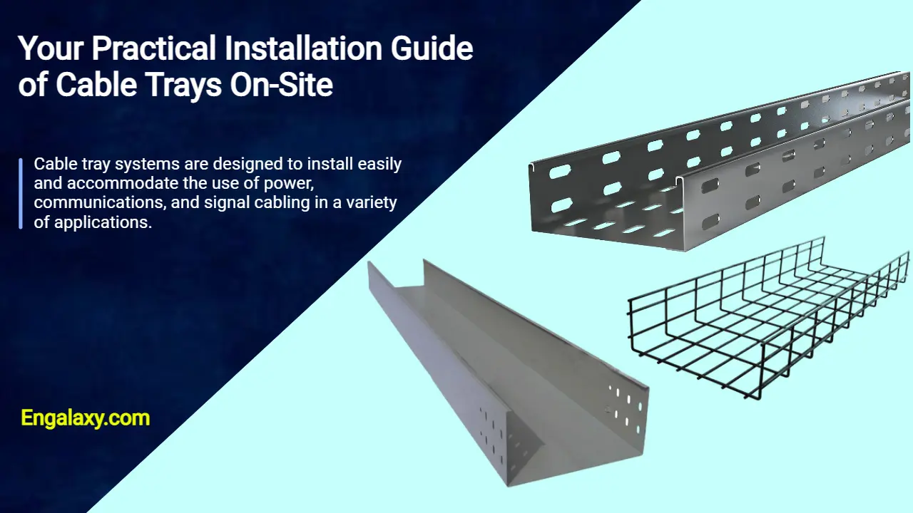
Cable tray systems are designed to install easily and accommodate the use of power, communications, and signal cabling in a variety of applications.
When properly installed, cable trays prevent damage to cabling and the area’s structural integrity. By being installed and engineered properly, cable trays also provide a safe and secure work environment for workers in any application.
In this post, we will see know together how to install cable tray on-site.
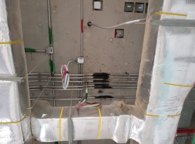
Firstly, we need to have an approved shop drawing that will show the cable tray route, its dimensions, installation height, support system, the number of layers of these trays, and the type of systems that these trays will serve.
In our example today, we will have two-layer support. The bottom layer will be a solid bottom cable trunk for electrical circuits with 150x100mm, while the upper layer will be a basket tray for a structured cabling system with 150x100mm.
You need to know that we need to maintain a vertical space between the basket tray and the cable trunk with a minimum distance of 30 cm.
This is because we need to avoid any interference between the electrical waves and telecommunication signals.
The next step is to check your project’s coordination drawings at the location of the installations.
We need to ensure no clash between the cable trays and the other services like HVAC ducts, Firefighting pipes, drainage systems, etc.
If we find any clash, we shall make a coordination meeting with the responsible engineer to solve the problem before starting the work.
Each engineer shall bring their systems drawings and check how to avoid this clash on-site.
Let us consider no clash on site, and the drawings are Ok, so you can instruct your team to proceed with the installation process.
But before the installation process starts, you need to check the availability of these materials in your project’s store.
If they are available and approved by the project’s inspector, you need to issue them from the store and send them to the working area in the project.
Also, we need to ensure that we have all the required hand and power tools to perform the job ideally.
We can divide these materials into two categories:
- A- Consumable materials.
- B- The permanent materials
So, I will now briefly describe the different required tools and the different categories of materials.
I- Tools:
We will need some hand and power tools to complete the support system installation.
These hand tools are summarized as follows:
01- Measuring tape: We will need it to measure the length or height, either the required length to cut the channels or threaded rods or the height needed to install the support system of cable trays.

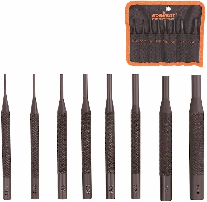
02- Hammer: We will need it to install the drop-in anchor or unifix inside its hole with the help of a pin punch.

03- Pin Punch: We will use it to ensure the unifix or the drop-in anchor completely fits its hole in the concrete slab.
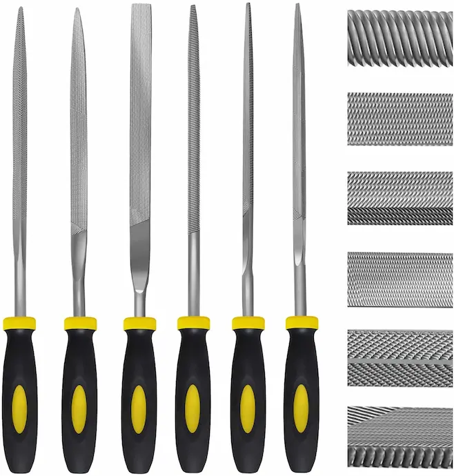
04- Metal File: We will need it for filing any sharp edges after cutting.
05- Chalk line or Line Dori: We will use it to create a straight line for the trays’ support system route.

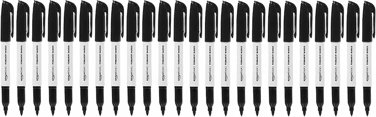
06- Permanent marker: We will use it to mark the locations of the holes and make a mark on the threaded rods and the Unistrut channel for the required length to cut.
07- Vise Grip: We will use it to catch the threaded rod and rotate it to ensure it’s completely inserted inside the drop-in anchor.

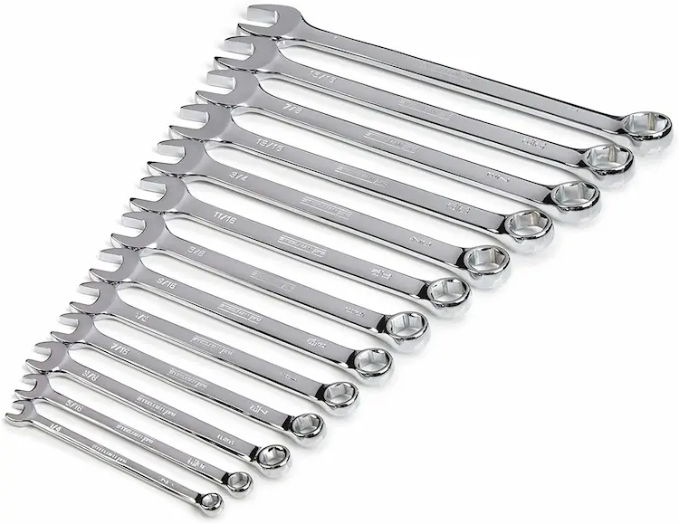
08- Spanner: We will use it to rotate and tighten the hexagonal nut with its threaded rod.
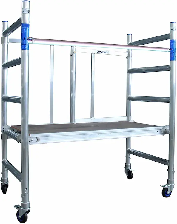
09- Steel or Aluminum scaffolding: We will use it to work at a high level.
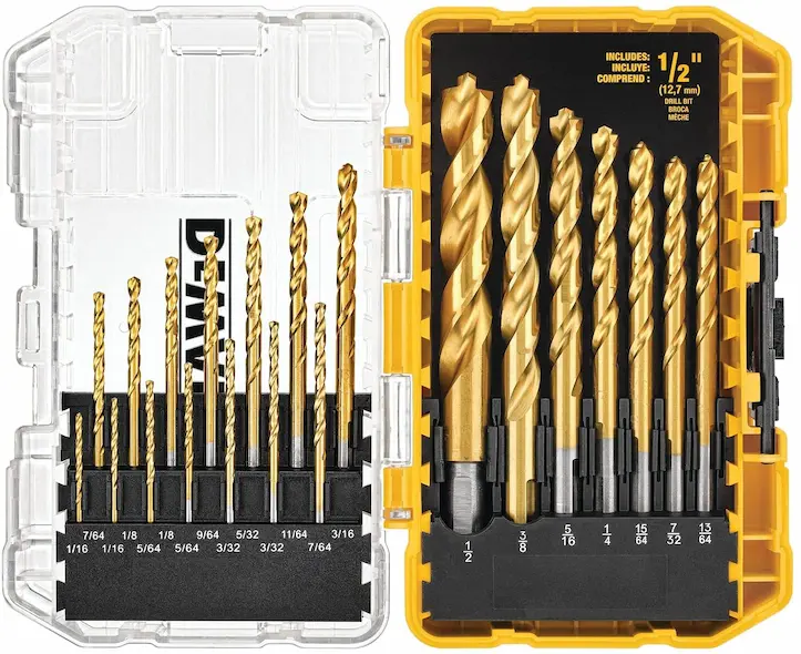
10- Concrete Drill Bit: This bit its size will depend on the size of the drop-in anchor. If the drop-in anchor’s inner diameter is 10mm and the threaded rod’s outer diameter is 10mm, the concrete drill bit will be 12mm.
11- Knockout hole punch: We will use it to make a hole in the cable trunk to connect a pull box for each circuit that will be pulled inside.

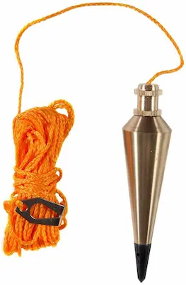
12- Plumb bob: We will use it to transfer the marking on floors to be typical on the soffit of the concrete slab.
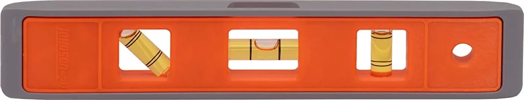
13- Spirit level: We will use it to check the leveling of the support installation to ensure it’s completely horizontal without any slope.
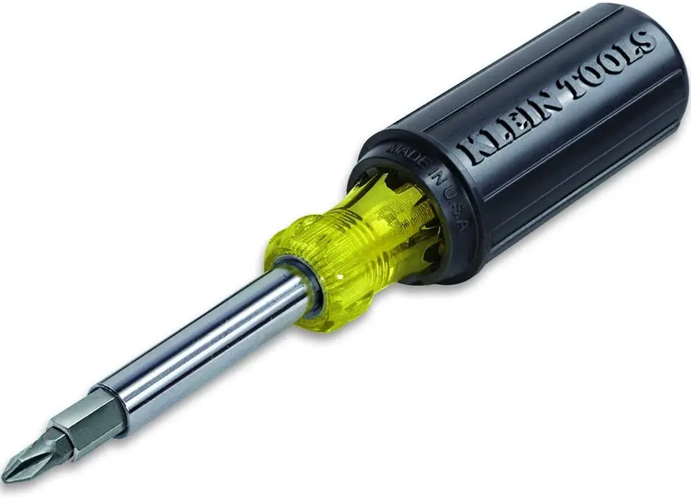
14- Screw Driver: We will use it to tighten the different screws, like the screw connecting the cable trunk with the Unistrut channel or the screw which connects the cable basket bracket with the spring nut.
And the power tools are summarized as follows:
1- Combination Hammer Drill Machine: either battery-powered or electrical powered. We will need it to drill the locations of the holes for the support system.
2- Angle Grinder complete with a steel cutting disk: We will need it to cut the Unistrut channel and the threaded rods at specific lengths per on-site requirements.
3- Crossline Combi Laser Machine: We will need it to mark where we need to drill the holes for the support system.
This is the summary of the hand & Power tools to be used for installing the cable trays on-site:
| Device Name | Brand Name | Learn More |
|---|---|---|
| Measuring tape | Stanley | Check On Amazon |
| Hammer | Estwing | Check On Amazon |
| Pin Punch | HORUSDY | Check On Amazon |
| Metal File | Kapoua | Check On Amazon |
| Chalk Line or Line Dori | Stanley | Check On Amazon |
| Permanent marker | Amazon | Check On Amazon |
| Vise Grip | Eagle | Check On Amazon |
| Spanner | Steelman | Check On Amazon |
| Aluminum scaffolding | Alumexx | Check On Amazon |
| Concrete Drill Bit | Dewalt | Check On Amazon |
| Knockout hole punch | Greenlee | Check On Amazon |
| Plumb bob | Swanson | Check On Amazon |
| Spirit level | Johnson | Check On Amazon |
| Screw Driver | Klein Tools | Check On Amazon |
| Combination Hammer Drill Machine | AOBEN | Check On Amazon |
| Angle Grinder | Black & Decker | Check On Amazon |
| Crossline Combi Laser Machine | Bosch | Check On Amazon |
B- Consumable Materials:
01- Unistrut channel: We will need to carry the cable trunk and basket tray load complete with their cables and wires.
02- Threaded Rods: They will be used to carry the Unistrut channels and their loads.
03- Drop-in anchor: It will be used to hang the threaded rods complete with their loads.
04- Flat washers and hexagonal nuts will be used to ensure the completed support system is connected. Their sizes will be the same size as the threaded rod.
05- Spring Nut or Wing Nut: It will be used to hold the cable trunk and basket tray with the Unistrut channel.
06- Hold Down bracket: We will use it to hold the basket tray with the spring nut that is installed inside the Unistrut channel.
07- Junction or Pull box: We will attach it to the cable trunk for the professional connection of the metal conduit with the cable trunk.
08-Brass Male bush: We will use it to connect the junction box with the cable trunk.
09- Insulated bushing: We will use it to be installed at the end of the brass male bush to avoid any sharp edges while pulling the wires inside the cable trunk.
10- Spray paint: We will use it for labeling the cable trunk at its bottom for better identification, especially if we have multiple systems with different cable trunks like lighting system, normal power system, UPS, etc.
C- Permanent Materials
1- Solid bottom cable tray or cable trunk complete with its fittings and accessories.
2- Basket Tray, or sometimes they call it wire mesh cable tray complete with its fittings and accessories.
Now we will see how to install this support system step by step.
01- The technicians will identify the route of the trays and the support system size based on the width of the trays.
02- They will mark on the floor the route of the trays, then they will identify the locations of the support system of the trays on the floor, and after that, they will transfer these markings to the soffit of the slab using a plumb bob or the cross line combi laser machine.
03- As per the width of the widest cable tray on the same support, they will cut the Unistrut channel, and also they will cut the threaded rods to the required length to achieve the installation height of the support with maintaining some extra distance for any modification later.
04- As I said earlier at the beginning of this video, the upper layer will be a basket tray with a size 150×100, and the cable trunk at the bottom layer will have the same width.
05- For example, if the concrete slab’s soffit height is three meters, and the cable trunk, which is the bottom layer, will be installed at the height of 2.1 meters, which means its distance from the soffit is 300 cm – 210 cm = 90 cm.
And as the height of the Unistrut channel is 2.1cm, and we need around 2 cm of the threaded rod to be inserted inside the drop-in anchor, so the minimum required length of the threaded rod is 2+90+2.1 almost equals 95 cm.
But we need to add 10 cm more to the total length of the threaded rod as a safety factor so that the technician will cut the threaded rod at a distance of 105cm.
06- As the width of the cable trunk and the basket tray is 15 cm, plus we need to give around 3 cm right and left the cable trunk for proper alignment, so the total length of the Unistrut channel that will carry the cable basket and the cable trunk will be 15+3+3= 21cm.
07- After the technician marked the locations of the threaded rods of the support system, he will start to drill the holes to install the drop-in anchor.
08- The technician uses a battery-powered hammer drill machine to drill the required holes to install the drop-in anchor.
09- After the technician has drilled many holes, he will install the drop-in anchor and use the battery-powered hammer to ensure the drop-in anchor will be inserted entirely inside the concrete slab. Also, you can use a hammer with a pin punch to do the same function.
10- The technicians will prepare the support system, as we have two layers. Hence, they need to use two threaded rods. Each of them will be 10mm per the approved support system schedule.
Also, they need to use two Unistrut channels. Each threaded rod will need five flat washers and five hexagonal nuts. Their size is 10mm, the same size as the threaded rods, so the total is ten flat washers and ten hexagonal nuts.
11- They will need one spring nut to be inserted at each Unistrut channel so that the total will be two spring nuts.
12- As you can see, they are installing flat washers and hexagonal nuts.
13- They will insert the threaded rods inside the drop-in anchors.
14- After that, the technician will use the vise grip to rotate the threaded rod inside the drop-in anchor to ensure it’s already completely inserted.
15- After that, the technician will use the spanner to tighten the nuts at the different locations, at the drop-in anchor, above, and under the Unistrut channel.
16- They will do the same at all the locations of the support system.
17- After that, they will fix the cable trunk and basket above their respective Unistrut channel with the help of the spring nuts.
18- In the end, the junction boxes will be attached to the side of the cable trunk, while for the basket tray, a pipe connection bracket will be used.
At the end, if you would like to read more about the cable trays installation, so you can get more information by reading this method statement which is available on this link:
https://link.engalaxy.com/method-statement-trays