This is a new electrical method statement in which I explain in details the MV cable joint or splicing of MV cables.
1- Contractor Details
The works will be undertaken by the contractor.
2- Scope of Work
Our total scope of work is to make jointing of MV Cables at all relevant areas according to approved design drawings, project specification,s and approved material submittals for the satisfaction and approval of the Consultant.
The work shall include not only the major items of the system but shall also include all the incidental sundry components necessary together with the resources for the complete execution of the works and for the proper operation of the installation whether or not these sundry components are stated in details.
This method statement of MV cable joint describes safe practices specifically pertaining to the jointing of MV Cables at all relevant areas.
All the activities in this method statement will be undertaken by a competent person.
3- Programmed Duration of Activity
All activities shall be done according to the approved project schedule.
4- Management Structure/Resources and Responsibilities
All the material will be available in the store, work will be done under the supervision of:
Name 1: Position:
Name 2: Position:
Name 3: Position:
5- Communication/Contact Details
Name: Mobile: Position:
Name: Mobile: Position:
Name: Mobile: Position:
6- Material
Ensure that all materials are stored and inspected with a complete approved inspection test plan (ITP) from the manufacturer before installation.
7- Method Statement – MV Cable Jointing
7.1- M.V. CABLE JOINTING
7.1.1- PURPOSE
To describe the procedure and jointing process associated with electrical activities.
7.1.2 SCOPE
This procedure shall be applied to the electrical works of the project which includes the medium voltage cable jointing of new cables for electrical equipment.
7.1.3 GUIDELINES
All electrical work shall be carried out in conformance with the Scope of Work, International Electrical Code (IEC), and the appropriate standard specification.
A qualified and experienced Electrical Engineer shall monitor all electrical activities related to Medium Voltage Termination Works assisted by an approved QC inspector and shall ensure that all the requirements are adhered to during termination activities.
7.1.4 CABLE JOINTING
Before Starting of Jointing
- Check to ensure that the kit you are going to use fits the cable.
- Refer to the kit label and the title of the installation instructions.
- Carefully read and follow the steps in the installation instruction.
- Double check the Size and routing of cable as per cable and conduit schedule.
- Ensure Megger Testing has been done and accepted.
- After termination high pot test should be carried out and recorded.
- Ensure that all termination works adheres to acceptable IFC drawings (Single Line Diagram and Elementary Diagram) and comply with applicable standards.
- All personnel who carry out termination work shall be certified.
General Instructions
- Use a propane (preferred) or butane gas torch.
- Ensure the torch is always used in a well-ventilated environment.
- Adjust the torch to obtain a soft blue flame with a yellow strip.
- Pencil-like blue flames should be avoided.
- Keep the torch aimed in the shrink direction to pre-heat the material.
- Keep the flame moving continuously to avoid scorching the material.
- Clean and de-grease all parts that will come into contact with adhesive.
- If a solvent is used follow the manufacturer’s handling instructions.
- Tubing should be cut smoothly with a sharp knife leaving no jagged edges.
- Start shrinking the tubing at the position recommended in the instruction.
- Ensure that the tubing is shrunk smoothly all around before continuing along the cables.
- Tubing should be smooth and wrinkle free with inner components clearly defined.
Step 00: Starting of Jointing
Cut the cable to the required length and remove the outer sheath as per the instruction of the termination kit manufacturer. The termination kit should be selected according to the system voltage and type of connection.
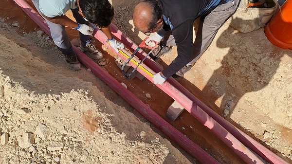
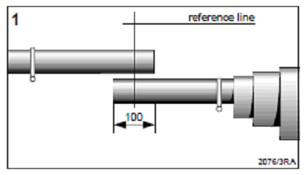
Step 01: Cable preparation
Overlap the cables to be jointed by 100mm. Mark the reference line (the middle of the overlap).
Slide the shortest of the three sealing sleeves over the short side of the joint. Fold and tape it down temporarily so that the next sealing sleeves can be slid over it.
Tape down the second sealing sleeve over the first one. Position the remaining sealing sleeve over the two sealing sleeves.
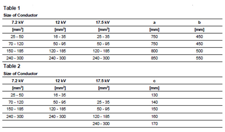
Cutback dimensions:
Remove the over sheath and armour according to the dimensions given in drawing A (table 1) by the manufacturer.
Remove the bedding up to 10mm from the armour cut. Do not cut the earth conductor (if any). Slide the screw clips over the cable ends.
Secure the ends of the armour wires with a wire bender.
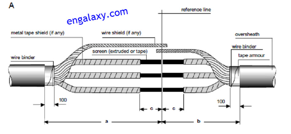
A- Cables with wire shields:
Twist the shielding wires together to form an earth conductor.
B- Cables with metal tape shields:
Remove the metal tape shield according to the dimension C given in Table 2
Shape and position the cores as shown in drawing A and cut them as the reference line.
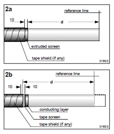
Step 02: Core Preparation
2a- Cables with extruded semi-conducting screen
Remove the extruded semi-conducting screen according to the dimension d as shown in table 3.
Note: Do not rick the insulation! Clean and degrease the insulation.
2b- Cables with semi-conducting tape screen and conducting layer
Remove the semi-conducting tape screen according to the dimension d as shown in table 3.
Note: Do not rick the insulation!
Cover the end of the semi-conducting tape screen and the first 10mm of the conducting layer with the plastic tape (adhesive side outwards). Completely remove every trace of the conducting layer. Use a solvent recommended by the cable manufacturer (preferably non-flammable).
Remove the plastic tape.
Step 03: Cables with extruded semi-conducting screen
Wrap plastic tape (adhesive side outwards) around the insulation 20mm from the end of the extruded screen.
Cover the 20mm length of insulation and about 5mm of the extruded semi-conducting screen with conductive paint.
Wait until the paint has dried and then remove the plastic tape.
B: Cables with a semiconducting and conducting layer
Cover the 20mm of conducting layer and about 5mm of the semi-conducting tape screen with conductive paint.
Compression (crimped) type connectors shall be used for terminating stranded conductors and shall be tinned copper type.
All Compression connectors for 8AWG and larger conductors shall have a manufacturer’s reference compression die number and conductor size printed or stamped on the connector.
For number 4/0 and larger conductors, compression terminal connectors shall be a two-hole NEMA design.
Single-hole compression terminal connectors are permitted for termination on manufactured equipment that has integral provision for single-hole lugs only.
For cable lugs, 120mm² and above, high-pressure compression or hydraulic crimping shall be used.
Step 04: Completion of Joint
Slide one combined tubing set over each long core end.
- Stress Control Tubing (Black)
- Insulating Tubing (Red)
- Screened Insulating Sleeves (Black and Red)
Step 05: Removal of insulation
Remove the insulation according to the dimension I=half length of connector whole + 10%
Joint the conductors by crimping, soldering, or any other equivalent method.
Remove any sharp edges.
Clean and degrease the insulation.
For maximum dimensions of connectors, see table 4.
Step 06: Removal of paper
Remove one release paper from the void filling compound (yellow) and roll it up.
Warp it around the connector with a 50% overlap stretching it to about half of its original width.
Fill up the connector areas continuing onto the insulation for more than 5mm.
Note: Do not use too much void-filling compound. The final diameter should be only slightly greater than the core or connector diameter, whichever is larger.
Step 07: Applying Silicon grease
Smooth out the surface of the insulation with a thin film of silicone grease. Slide the stress control tubing (black) over the completed connector area before taping the other cores.
Step 08: Installation of Stress Control Tubing
Position the stress control tubing (Black) centrally over the connectors.
Strat shrinking in the center working towards the ends.
The tubing should be fully shrunk and wrinkle-free.
Note: Take care not to accidentally shrink the other tubing at this stage.
Step 9: Installation of The Red Insulation Tubing
Pull the insulating tubing (red) from the inside of the screened tubing (black and red) and position it centrally over the stress control tubing.
Start shrinking in the center working towards the ends.
Note: Continue immediately with step 10 while the insulating tubing is still hot.
Step 10: Shrinking the screened Insulation Tubing
Position the screened insulating tubing (blade and red) centrally over the previously installed tubing.
Start shrinking in the center working towards the ends. The tailing should be fully shrunk and wrinkle-free.
Step 11: Installation of the armoring above the joint
A. Cables with Wire Shields:
Relay the cores as far as possible.
Wrap all the copper braid around the cores with a 60% overlap so that the whole joint area is covered.
Joint the earth conductor by crimping or any ether equivalent method.
B. Cables with Metal Tape Shields:
Wrap two layers of the copper braid with a 50% overlap round
each joint area, continuing for 20 mm onto the metal tape
shield.
Attach the copper braid to the metal tape shield on both sides of the connector area by soldering or any other equivalent method (such as Raychem solderless earth connection, see EPP 0184). to maintain shield continuity. Relay the cores as far as possible.
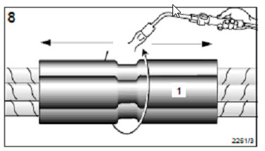
Step 12: Installation of the Joint Case
Wrap the joint case around the joint and secure it with about two layers of cloth tape as shown in the picture.
Clamp the ends of the joint case onto the steel tape armour using the screw dips.
Cover the sharp edges of the screw dips by fastening a piece of cable over the sheath over the screw with the remaining doth tape.
Step 13: Installation of the Long Sealing Sleeve
Slide the top long sealing sleeve over the long side of the joint.
Position the sleeve so that it overlaps for 100 mm onto the over sheath.
Shrink it into place start ng from the joint area and world ng towards the over sheath.
Step 14: Installation of the second Long Sealing Sleeve
Position the second long sealing sleeve over the center of the joint.
Overlap the previously installed sealing sleeve by 100 mm. Start shrinking in the center working towards the ends.
Step 15: Installation of the Short Sealing Sleeve
Position the short sealing sleeve over the short side of the joint. Overlap the over sheath by approximately 10 mm. Start shrinking at the joint area working towards the over sheath.
Step 16: Wait until Cooling the joint
Allow the joint to cool before applying any mechanical strain.
Note: Please dispose of all waste according to environmental regulations.
General Notes on MV Cable Joint :
- Ensure there is no cracking or damage to cable lugs on applying the pressure. Wrap with rubber tape and vinyl electrical tape around the barrel of the cable lugs.
- Arrange, install and terminate the cable to the designated terminal point and ensure the correct phase line sequence between cables and terminal.
- Use mechanical connectors supplied as an integral part of splice and termination kits. Adhere to the installation instruction of the kit manufacturer.
- The steel surface shall be thoroughly cleaned before making a grounding connection.
- Conduit openings around cable connection points shall be sealed with a duct seal compound.
8- Inspection and Test Plan (and Quality Records)
Prior to jointing of the cables, physical inspection, and phase identification/verification.
9- Plant and Equipment
- Cutting Tools
- Crimping Tools
- Gas Torch
- Hand tools.
10- Training and Competency of Personnel (see also 13 below)
The work will be carried out with professional and skilled technicians
11- Advise Any Permits to Work required (e.g. Hot works; confined space; excavation; electrical)
To be assessed at the time of work.
12- Waste Management
Housekeeping shall be done on daily basis, solid waste will be segregated.
13- Testing and Commissioning
After a successful installation inspection Request will be raised.
14- Supporting Documents:
- Risk Assessment (attached).
- Certificates and licenses for personnel are available on request.
- Approved drawings.
This is the end of the MV cable Joint method statement, You can read also:
Metered Ring Main Unit T&C Method Statement
Busway Testing and Commissioning Method Statement
1st Fix Installations Method Statement for Electrical and Low Current Systems
All our method statements are available on this link:
https://engalaxy.com/method-statements
Join Our Professional Email List to be notified of the New Courses, Free Downloads, Articles…..and much more
MV cable joint MV cable joint MV cable joint