1.0 PURPOSE:
This method statement is applicable for installing the fire resistance cables and devices for the fire alarm system and Emergency lighting system in all applicable areas for the Project of the building.
2.0 SCOPE:
Supply and install the fire resistance cables and devices of the fire alarm and emergency lighting systems for all applications in line with project requirements.
3.0 REFERENCES:
- The Latest Approved shop drawings for the required and applicable areas for the fire alarm and voice evacuation system and shop drawings for the Emergency lighting system.
- Specification:
- Agreement:
- Manufacturer’s Recommendation.
- Project Quality Plan
- Regulation of the local Electrical Authority,
- Requirements of Civil Defense or Fire Department.
4.0 DEFINITIONS:
Client:
Contractor :
Sub-Contractor :
PQP : Project Quality Plan
PSP : Project Safety Plan
PPE : Personal Protective Equipment
HSE : Health, Safety, and Environment
MS : Method Statement
ITP : Inspection Test Plan
QA/QC : Quality Assurance / Quality Control Engineer.
5.0 RESPONSIBILITIES:
Responsibilities for ensuring that the steps in this procedure shall be carried out at appropriate steps in the procedure:
· Project Manager
· Construction manager
· QA/QC Engineer
· Site Engineer
· HSE officer
5.1 Project Manager
– The work progress shall be carried out as per the planned program, and all the equipment required to execute the works shall be available and in good condition as per Project planned.
– Specific attention is paid to all safety measures and quality control in coordination with Safety Engineer and QA/QC Engineer, and the client’s representative.
5.2 Construction Manager
– Construction Manager is responsible for supervising and controlling the work on site.
5.3 Site Engineer
– The method of statement to the system shall be implemented according to the project specifications and approved shop drawings.
– Provision of all necessary information and distribution of responsibilities to the Construction team.
– The work progress shall be monitored following the planned work program, and the Engineer will provide reports to his superiors.
– The constant coordination with the Safety Engineer ensures that the works are carried out in a safe working atmosphere.
– The constant coordination with the QA/QC Engineer for any works to be carried out and initiate the Inspection for the finished works.
– He will ensure the implementation of any request that the client/consultant might raise.
– The Site MEP team shall obtain Efficient daily progress for all the equipment and manpower.
– He will engage in the work and check the same against the daily report received from the Foremen.
– The passage of all the revised information to the Foremen and ensure that it’s being carried out properly.
5.4 QA/QC Engineer:
– The monitoring of executions of works at the site should be as per the approved shop drawings and project specifications.
– Ensure inspections for material and work are being raised for activities on time and inspected by the consultant.
– He will follow and carry out all the relevant tests per project specifications.
– Obtain the required clearance before inspections.
– Should acquire any necessary civil works clearances and coordination.
5.5 Site Foreman
– The carrying-out of work and the proper distribution of all the available resources in coordination with the Site Engineer daily.
– Daily reports of the works are achieved and coordinated for future planning with the Site Engineer.
– Incorporate all the QA/QC and Safety requirements as requested by the Engineer.
– Meeting with any unforeseen incident or requirement and reporting the same to the Site Engineer immediately.
5.6 Safety Officer
– The implementation of all safety measures following the HSE plan and that the whole workforce is aware of its proper implementation.
– The implementation of safety measures is adequate to maintain a safe working environment for the work activity.
Inspect all the site activities and train personnel in accident prevention and its proper reporting to the Construction Manager and the Project Manager.
– Ensure the site is maintained in a clean and tidy manner.
– Ensure only trained persons shall operate the power tools.
– Ensure all concerned personnel shall use PPE and all other items as required.
– Ensure adequate lighting is provided in the working area at night time.
– Ensure high-risk elevated areas are provided with barricades, tape, safety nets, and ladders.
– Ensure service area/inspection area openings are provided with barricades, tape, and safety nets.
– Ensure safe access to site work at all times.
5.7 Store Keeper
– Responsible for overall Store operations in making sure to store the material delivery to the site and keep it in a suitable area that will keep the material safe from rust and damage.
6.0 EQUIPMENT:
§ Power source
§ Drilling machine
§ Tool Box
§ Measuring Tape
§ Calibrated Ohm Meter / Multimeter
§ Ladders / Scaffoldings
§ Hammer
§ Safety requirements include safety shoes, safety helmets, safety glasses, fluorescent vest, and safety gloves to ensure the maximum ability of safe work and a dust mask when required.
7.0 PROCEDURE
7.1 Safety
- Ensure only trained persons shall operate the power tools.
- Ensure all concerned personnel shall use PPE and all other items as required.
- Ensure adequate lighting is provided in the working area at night time.
- Ensure service area/work area openings are provided with barricades, tape, and safety nets.
7.2 Work Sequence And Methodology
- Check all material delivered to the site is inspected correctly by QA/QC Engineer and check if it is appropriately stored as per the manufacturer’s recommendations.
- An inspection request shall be raised for the Inspection of materials received at the site from the client.
- The site staff shall carry out work under strict supervision and guidance of the concerned Supervisors / Foremen / Engineers.
- The QA/QC Engineer shall check all the installations per the Installation Checklist.
- Inspection request shall be prepared by QA/QC Engineer and submitted to consultant for their Inspection and approval by coordinating with other contractors and arranging Inspection for the finished work.
7.3 Handling and Storage
- Upon receipt of the materials at the site, necessary precautions shall be taken for unloading, shifting, and storage, as follows:
- Material shall be stored in a covered/dry space to avoid being damaged.
- All materials received at the site shall be inspected and ensured that the materials are as per approved material submittal.
- Any discrepancies, damage, etc., found will be notified and reported for further action.
- The material found not suitable for site use will be removed from the site immediately.
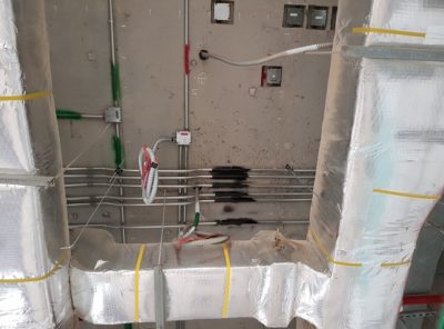
7.4 Installation of the Fire resistance Cables:
- The correct size of the Fire Resistant Cables shall be ascertained from approved shop drawings before installation.
- Fire resistance cables shall not be drawn into the same conduit, trunking compartment, or ducting compartment as cables of other systems.
- We will use Red color cables for the fire alarm system and white cables for the Emergency lighting system.
- We will use 2X 1.5mm2 fire resistance cable to terminate the fire alarm detectors with the Fire alarm panel board and 2X 2.5mm2 fire resistance cable to terminate the emergency lighting to the Central battery panels and sounders to fire alarm panels.
- While we will use fire-rated cables to connect the main distribution board and the Central battery panels.
- Before pulling cable in existing / new conduit, ensure that the conduit has been inspected and is free from any sharp edges.
- Mark the location of the Fire Resistant Cable on the floor/slab/walls/structure as per the approved layout drawing.
- Fix the single proprietary clips for a single run of cable or two holes clip formed from fixing strip covered with plastic with screws and wall plugs. The distance between clips shall be as recommended by the manufacturer.
- Where Fire Resistant cables pass through concrete, blockwork, walls, floors, etc., they shall be suitably protected by a length of PVC conduit throughout the concealed length. Whereas in existing floors, concrete, blockwork, walls, etc.
- No Fire Resistant Cable shall be installed directly in the concrete, blockwork or brickwork, walls, floors, etc., without the written permission of the consulting Engineer.
- PVC Conduits are not required when Fire Resistant cables are installed in false ceilings, floors, or within dry-type partitions.
- All cables shall run in straight lines parallel and square with the lines of the building. Where the Engineer permission is given for cables to be concealed within plastered or rendered walls, they shall be routed in straight lines parallel to the floor or ceiling and plumb vertical down walls Cables shall be continuous without any through joints.
- After the fire resistance cables are installed, these will be tested for continuity and insulation resistance before the termination of fire resistance cables to the devices.
7.5 Termination of Fire Resistant Cables will be carried out as per manufacturer’s
instructions:
- With a sharp knife, score the circumference of the outer sheath and Bend the Fire Resistant Cable on score marks so that the outer sheath breaks. Lightly score the aluminum tape and bend the cable again so that the tape tears.
- Twist and pull to remove the outer sheath.
- With the outer sheath removed, now unwind and remove any remaining tape.
- Separate the conductors and strip the insulation from the conductors for the required length.
- The Fire Resistant Cable is now ready to fit the gland and terminates to the equipment/device.
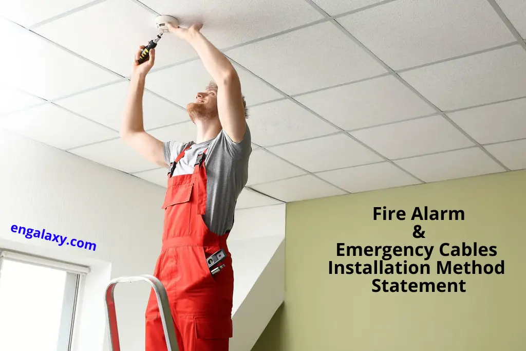
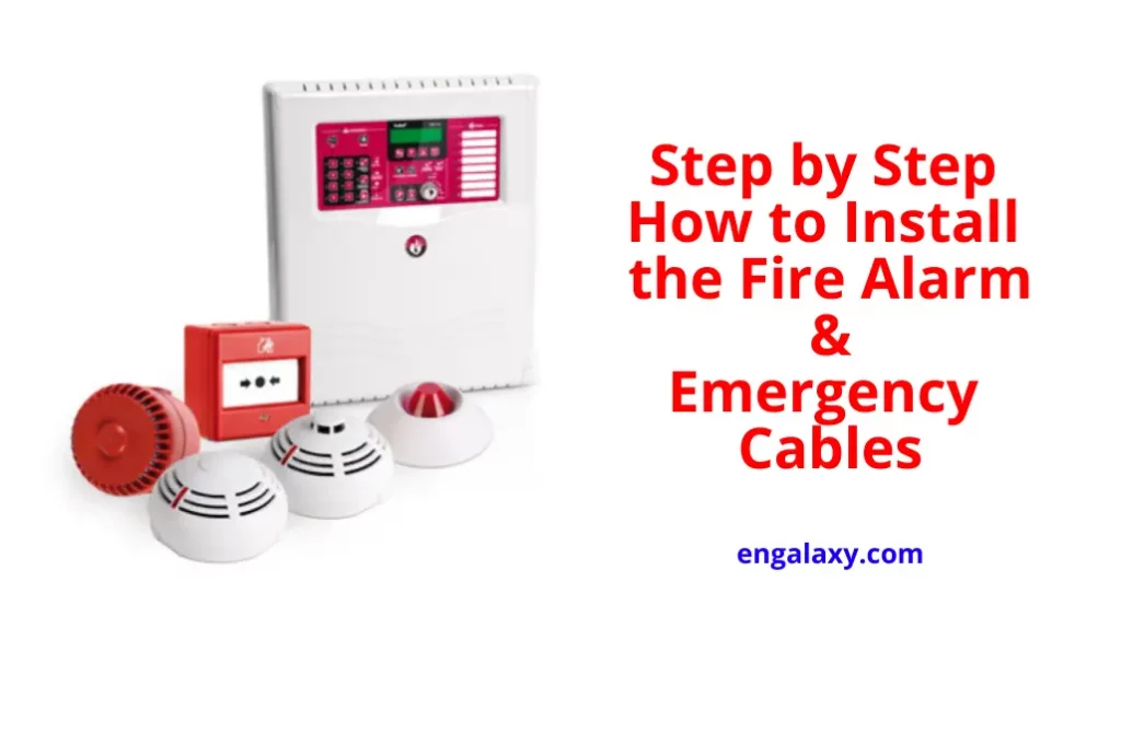
7.6 Installation Of FA Devices:
- The devices/peripherals (Smoke detectors, heat detectors, break glass, duct detectors, beam detectors, control, and monitoring modules) are connected in a Class A circuit with the Control panels.
- The speakers & speakers with strobes are connected in a Class A circuit with the Control panels.
- 2 Core 1.5mm2 FP 200 cable to be used for cabling the Initiating Device Circuits (IDC) to the panel; an additional 2c x 2.5mm2 FP200 cable is required for the smoke detector with sounder base for the activation of the sounders units.
- Two core 1.5mm2 FP 200 cables are to be used for cabling the Speakers with the panel, and an additional 2c x 2.5mm2 FP200 cable is required from the FACP for the speaker with strobe for the activation of the strobe unit allied in vertical walls the run of conduit will be kept straight.
- Comply with NFPA 72 for the installation of fire alarm equipment.
- Smoke- or Heat-Detector Spacing:
- 1. Comply with NFPA 72, “Smoke-Sensing Fire Detectors,” & “heat-sensing Fire Detectors.”
- 2. Smooth ceiling spacing shall not exceed 30 feet (9 m).
- Fire-Alarm Control Unit: Surface mounted, with tops of cabinets not more than 72 inches (1830 mm) above the finished floor.
- Annunciator: Install with the top of the panel not more than 72 inches (1830 mm) above the finished floor.
FIRE ALARM CONTROL PANEL
· Install the semi-recessed Backbox provided at the location as per the approved shop drawings.
· Power supply for the FACP shall be through an un-switched SPUR outlet located above the FACP concealed above the false ceiling. The un-switched SPUR switch shall be a separate branch circuit.
· The Backbox must be dust free and clean before dropping all the field cables inside the Backbox.
MANUAL CALL POINT
· Install the recessed recommended 2″ x 4″ back box at the locations as per the approved shop drawings.
· Install and terminate the Manual call point per the manufacturer’s instructions.
CONTROL & MONITOR MODULES
· Water-Flow Detectors and Valve Supervisory Switch: Located near each sprinkler valve station and/or water flow detector that is required to be supervised. The module shall be mounted inside recommended 2″ x 4″ backbox and wired to the sprinkler valve station and/or water flow detector via GI flexible conduit.
· AHUS’, FAHU’S, Lifts, Access Controlled Doors, Public Address System, etc. Which is required to be controlled in case of a fire situation. The Control module shall be mounted inside recommended 4″ x 4″ backbox and wired to the equipment to be interfaced.
· Install and terminate the Monitor and Control modules as per the manufacturer’s instructions.
SMOKE & HEAT DETECTORS
· Ceiling-Mounted Smoke and Heat Detectors: No less than 100mm from a sidewall to the near edge. For exposed solid-joint construction, mount detectors on the bottom of joists. On smooth ceilings, install Smoke detectors not more than 9m apart in any direction and Heat detectors not more than 7m apart.
SOUNDERS & SOUNDER/FLASHER
· Install the recessed recommended 4″ x 4″ back box at the locations as per the approved shop drawings.
- Install and terminate the Sounders as per the manufacturer’s instructions
7.7 Fault Finding For Emergency Battery System
Battery Charger Faults:
Battery Charger Faults can arise during the operational lifetime of a panel. You may observe one of the following Faults; Charger 2% out of range Battery Charger Supply incorrect to correctly measure the output voltage; you will need to follow the steps below.
- To prevent damage to the system, disconnect the batteries & power down the system, and disconnect the power & harnesses from the Power Supply.
- Connect the Multi-meter to the battery leads (with batteries disconnected), power up & measure the voltage. Calculate the difference between the measured voltage & 27.6v. NOTE: After 90 seconds, the voltage will drop to <24v. If this happens, power down & start again.
Positive/Negative Earth Ground Faults:
Fire Panels can detect positive or negative Earth Ground Faults. An Earth Ground Fault occurs when an electrical circuit is shorted to the ground.
7.8 Inspection, testing, and commissioning
Specifications shall carry out all construction/inspection/testing works. The Site MEP team shall carry out under the guidance of a respected Engineer and shall further be checked and approved by QA/QC Engineer.
- Check all devices installed as per the specifications & Drawing.
- Visual Inspection: Conduct visual Inspection before testing.
- The Inspection shall be based on completed Record Drawings and system documentation as per NFPA.
- Comply with the “Visual Inspection Frequencies” Table in the “Inspection” section of the “Inspection, Testing and Maintenance” chapter in NFPA 72; retain the “Initial/Reacceptance” column and list only the installed components.
- System Testing: Comply with the “Test Methods” Table in the “Testing” section of the “Inspection, Testing and Maintenance” chapter in NFPA 72.
- Test audible appliances for the public operating mode according to the manufacturer’s written instructions. Perform the test using a portable sound-level meter complying with Type 2 requirements in ANSI S1.4.
- Test audible appliances for the private operating mode according to the manufacturer’s written instructions.
- Test visible appliances for the public operating mode according to the manufacturer’s written instructions.
- Factory-authorized service representative shall prepare the “Fire Alarm System Record of Completion” in the “Documentation” section of the “Fundamentals of Fire Alarm Systems” Chapter in NFPA 72 and the “Inspection and Testing Form” in the “Records” section of the “Inspection, Testing and Maintenance” chapter in NFPA 72.
- Reacceptance Testing: Perform reacceptance testing to verify the proper operation of added or replaced devices and appliances. Test all the field loop devices with the control panel.
- Check the detectors with the artificial test smoke spray.
- Use forms developed for initial tests and inspections.
- Field tests shall be witnessed by authorities having jurisdiction.
- Manufacturer’s Field Service: Engage a factory-authorized service representative to inspect, test, and adjust components, assemblies, and equipment installations, including connections.
- Perform tests and inspections.
- After testing & commissioning, provide training demonstration to the facility management team.
- Conduct Cause effect inspection as per programmed cause & effect matrix. Test all the connected devices’ responses as per the matrix.
- Identify system components, wiring, cabling, and terminals. Comply with requirements for identification specified in specifications.
- Install framed instructions in a location visible from the fire-alarm control unit.
- Ground fire-alarm control unit and associated circuits; comply with IEEE 1100. Install a ground wire from the main service ground to the fire-alarm control unit.
8.0 ATTACHMENTS
8.1 Inspection & Test Plan
8.2 Inspection Check Sheet
8.3 Risk Assessment
8.4 Manufacturer recommendations.
All our method statements are available on this link:
https://engalaxy.com/method-statements
Join Our Professional Email List to be notified of the New Courses, Free Downloads, Articles…..and much more
If You would like to learn more about the practical installations of the different MEP systems on-site, so have a look at our free MEP Mini-Course