Installing HVAC equipment is a complex process that requires careful planning and execution.
A well-executed installation can result in years of trouble-free operation.
While a poorly executed installation can lead to frequent repairs and downtime.
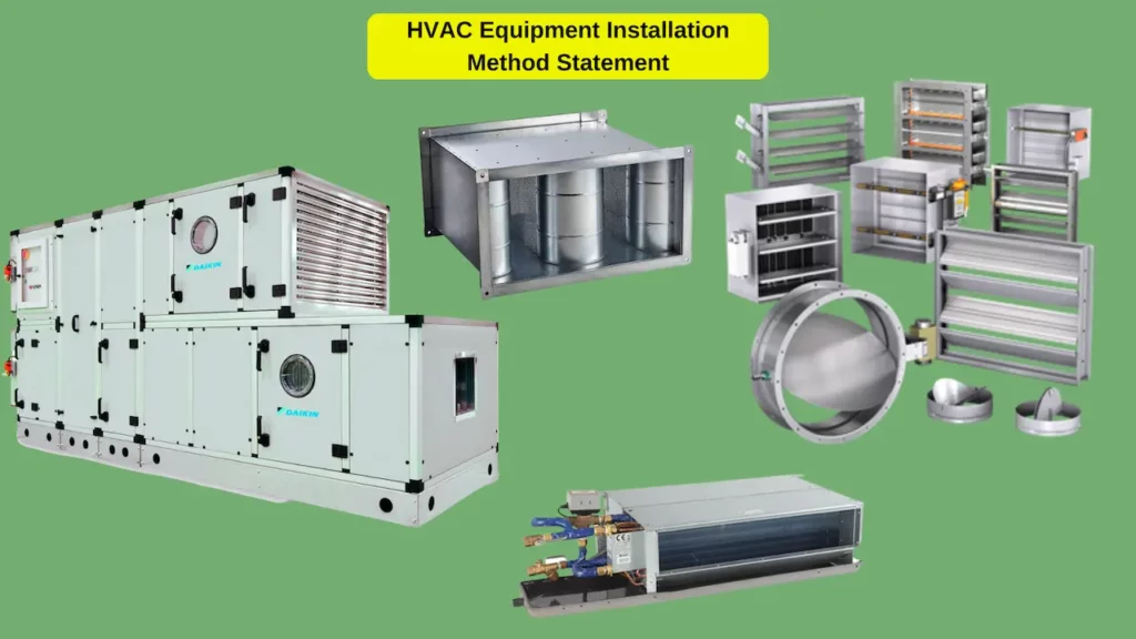
So, In this method statement, we will know how to install the Air Handling Unit / AHU, Fan Coil Unit / FCU, Dampers, Silencers, Grills, Diffusers, Registers, and Louvers on-site step by step.
01- Contractor Details
The contractor’s qualified personnel will initially undertake the work.
02- Scope of Work
This Method statement covers the Installation of Dampers, Silencers, Grills, Diffusers, and Louvers.
These installations will be followed as per the Manufacturers recommendation and as per the SECTIONS 15820 and 15855.
03- Programmed Duration of Activity
Works are to commence as per the latest approved schedule.
The overall site-wide Infra networks will take approximately 18 months to complete.
04- Management Structure/Resources and Responsibilities
Subcontractor Project will manage the overall works.
The subcontractor’s teams will control the lines and levels of the work.
Coring/Excavation will be managed and operated by the Main Contractor Plant & Equipment.
The installation will be carried out and managed by using Subcontractor labor.
05- Communication/Contact Details
You can contact us through the following personnel:
Main Contractor Personnel:
Name: Position: Mobile:
Sub-Contractor Personnel:
Name: Position: Mobile:
06- Method Statement/Procedure
The works will be completed as follows:
The Installation of Air Handling Units, Fan Coil Units, Dampers, Silencers, Grills, Diffusers, Registers, and Louvers will be followed as per sections in the specifications of the project:
15820 – Duct Accessories
15855 – Diffusers, Register & Grilles
15763 – Fan Coil Units
15854 – Central Station Air Handling Units
06.1- Delivery, Storage, and Handling
- All Air handling units, Fan coil units, Dampers, Silencers, Grills, Diffusers, Registers, and Louvers will be delivered in manufacturers’ original protective packaging.
- Upon receiving Chilled Water Pump Sets, the Site Engineer (HVAC) must ensure that all units, dampers, and air outlets received at the site are free of any damage or deformity of any kind.
Any minor damages observed will be repaired suitably, and if repairing perfectly is not possible, it will be sent to the supplier for rectification.
Furnish extra materials that match products installed, are packaged with protective covering for storage, and are identified with labels describing contents. - All materials received at the store will be inspected, and ensure that the materials are as per approved material submittals in terms of their make, model type, country of origin, and sizes.
- Use the appropriate types of vehicles or lifting machinery in transporting and unloading the air handling units, making, sure enough, manpower available.
- Upon arrival at the store, Dampers, Silencers, Grills, Diffusers, Registers, and Louvers will be off-loaded carefully using necessary manpower and equipment to ensure no damage is caused.
- Do not stack back draft dampers on top of each other. Do not drop, drag, or twist the dampers. Dampers are to be handled and lifted by the frames only.
- All material will be stored in a clean place with adequate covering. Covering will be done to protect the equipment from the deposition of construction dust until they are finally shifted to its location.
- Materials will be stored on a flat surface in a well-ventilated storage area.
- Fan coil units will be stored on their delivery packing and must remain in a horizontal orientation and the correct way up.
- The plastic end caps covering the supply/return coil will remain closed to avoid corrosion and deterioration.
- Aluminum fins are to be protected and checked regularly.
- All filters must be suitably wrapped and sealed to prevent dampness and ingress of dust or foreign matter and must be held in a dry store.
- Inspect the exterior casing of the AHUs, FCUs, Dampers, Silencers, Grills, Diffusers, and Louvers for any damages during transportation or shipping.
- All products that are found not under the specification shall immediately be removed from the site and replaced. Repair shall not be undertaken before the Consultant Engineers review the contractor’s proposed actions.
- Material Submittal will be approved for all material, equipment, and accessories prior to material fabrication and delivery.
- Material Inspection Request (MIR) will be submitted for materials delivered at the site prior to installation. Inspection will be based on material submittal approval.
The nameplate & identification number of the equipment will be checked during (MIR).
06.2- Pre-Installation Procedure
- Ensure that the work area is clean and safe for carrying out activities.
- After inspecting the work area, ensure that it is totally ready for installation.
- Ensure that the proper clearance is available from the civil construction side before the commencement of works.
- Prior to the start of work, ensure that the relevant shop drawings and coordination drawings are approved and issued for construction.
- It shall be ensured that there is no contradiction with other previously installed services, and if there is any shall be cleared before installation.
- Examine areas where diffusers, registers, and grilles will be installed to comply with requirements for installation tolerances and other conditions affecting equipment performance.
Once unsatisfactory conditions have been corrected, the installation will proceed. - Before installation of AHU, ensure that suitable access is available for routine maintenance and the removal of such items as coils, fans, and filters.
- Ensure that the required material at the site is approved.
- Then the required equipment will be moved to the place of installation.
- Ensure on-site lifting equipment such as mobile crane, forklift, and jock trolley is available.
- Ceiling-Mounted Outlets and Inlets: Drawings indicate the general arrangement of ducts, fittings, and accessories.
Air outlet and inlet locations have been indicated to achieve design requirements for air volume, noise criteria, airflow pattern, throw, and pressure drop.
Make final locations where indicated, as much as practicable.
For units installed in lay-in ceiling panels, locate units in the center of the panel. Where architectural features or other items conflict with installation, notify the engineer to determine the final location. - Examine roughing-in of steam, hydronic, and condensate drainage piping systems and electrical services to verify actual locations of connections before installation.
- Ensure sufficient slope to the drainpipe is available for easy draining of condensate drain.
- Ensure all safety requirements are met and followed as per approved Risk Assessment measures and control.
- Arrange proper tools and equipment. Make sure that all workers are wearing the required safety equipment.
06.3- Installation Procedure of Air Handling Unit or AHU
06.3.1 – Pre-installation of Air Handling Unit:
- Before installation of AHU, check the lifting gears are available at the site. The road which will be used to transfer the AHU is closed/barricaded.
- Make sure the concrete bases are approved and there is access to AHU/FAHU from all sides.
- Temporary protection must be provided to protect the openings during installation until final connections are made to the AHU/FAHU.
06.3.2 – Placing of AHU/FAHU on Concrete foundation:
- Place the anti-vibration rubber pads of the correct thickness or spring isolators as per approved drawings/submittals. In case of multiple rubber pads, the pads will be placed one above the other, with the ribs at a right angle.
- Mark the exact and correct location of AHU/FAHU point loads as per approved shop drawings. Then drill the hole on the foundations to match the equipment mounting holes per the AHU points load distribution.
- Clean the hole using an air source to blow the debris out.
- Drive the concrete anchor bolt into the hole using a hammer and ensure that the anchors are inserted firmly and rigid.
- The lifting point should be at the center of gravity of the AHU and FAHU load.
- Bring the AHU/FAHU to the foundation using a jack trolley and an adequate number of helpers to do the work efficiently.
- Carefully mount the unit by adjusting the height of the jack trolley on the rubber pads and concrete anchor bolt, and firmly fix the units with a concrete foundation by tightening the concrete anchor bolt.
- Align the units in both parallel and perpendicular directions.
06.3.3 – Joining sections of AHU/FAHU:
- If the units are shipped in multiple sections, the AHU/FAHU will be assembled strictly per the manufacturer’s instructions.
- The units are supplied in the section, and materials for joining the sections are provided inside the units delivered. Such as corner plates, L junctions, bolts, gaskets, etc.
- Apply the self-adhesive gasket to the aluminum unit frame of one of the two sections to be joined together.
- Screw the corner angle reinforcement plates together. Screw the L plate together.
- Fix all corner plate and L plates and ensure the section is firmly fixed with each other.
- Assembly of the remaining sections parts by part until all the unit is completed.
- Ensure that all AHU/FAHU sections are properly aligned and firmly fixed.
- Ensure that belt is installed properly and protected from damage.
- Upon satisfactory positioning of AHU/FAHU, any open air/water outlets will be closed properly, and the area will be cleaned, with complete protection in areas where other trades are working.
- Before connecting any ducting or piping, ensure that all bolts are tightened and the units are firmly fixed to the foundation.
- Filters such as Bags and pre-filter will be installed before inspection and then removed and stored until the pre-commissioning phase to protect them from dust and damage.
- Installation of humidifier and connection with the system if required.
- Inspection Request (IR) for installation of air handling units will be raised and forwarded to the consultant.
The inspection and witness will be as per project procedures.
06.3.4 – AHU/FAHU Duct Connection:
- The flexible duct connector will come in a roll, so cut a length equivalent to the perimeter of the duct required plus an overlap of 10 to 15 cm.
- Lift the seam outwards at a right angle, and cut at the seam section’s edge. Bend down the seam whilst ensuring that the cloth remains fastened.
- Connect the flexible duct connector with one end with a duct and another end with an air outlet using a flange joint.
- Install the sound attenuators in line with ductwork as per approved drawings.
Ensure the sound attenuators are installed in the direction of airflow and as per approved material submittal. - Provide adequate support to the attenuators and ensure they are properly aligned with the duct.
- Install the non-return damper, volume control dampers, and motorized fire smoke dampers in line with the duct as approved drawings.
- Protect the equipment after installation with thick polythene sheets or other protective material.
06.3.5 – Hook up of Chilled Water Connection:
- Hydronic piping, valves, and fittings will be installed as per approved shop drawings.
- Connect the chilled water pipes to the Air Handling units as per the approved drawing.
- Make sure that the hydro test of piping is completed before connecting to the Air handling unit.
- Use a dielectric union to connect the chilled water piping to the Air Handling Unit coils.
- After the union connects to the pipe flexible connector to avoid vibration of the unit passing in the piping.
- Provide all Test, tap, and drain points as per the approved drawing.
More and more information is available in this method statement,
Please click on the next button if you want the complete editable file ( Word File )of this method statement and other method statements.
Also, If you would like to learn the different Mechanical practical installations on-site, you can have a look at our Mechanical Practical Installations Online course from this link:
Also, you can find all our published method statements on this link:
https://engalaxy.com/method-statements/
If You would like to learn more about the practical installations of the different MEP systems on-site, so have a look at our free MEP Mini-Course