Revit MEP is a powerful software used in the construction and engineering industry to plan and design mechanical, electrical, and plumbing systems.
It has become an essential tool for building information modeling (BIM) professionals, making creating accurate and efficient designs easier.
However, for those who are new to Revit MEP, the user interface may seem daunting and overwhelming.
Understanding the user interface is crucial to operating the software efficiently and effectively.
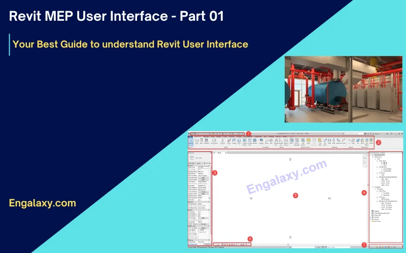
So, in this blog post, we will introduce the first part of the Revit MEP user interface, breaking down its key features and providing a comprehensive overview of the software’s interface.
We will explore the various tools and panels, outlining their purpose and functionality, and provide tips on navigating the interface quickly.
By the end of this post, you will have a solid foundation in the Revit MEP user interface, allowing you to move forward with confidence and a deeper understanding of the software’s capabilities.
As you can see in this photo, we have seven main windows in the Revit interface.
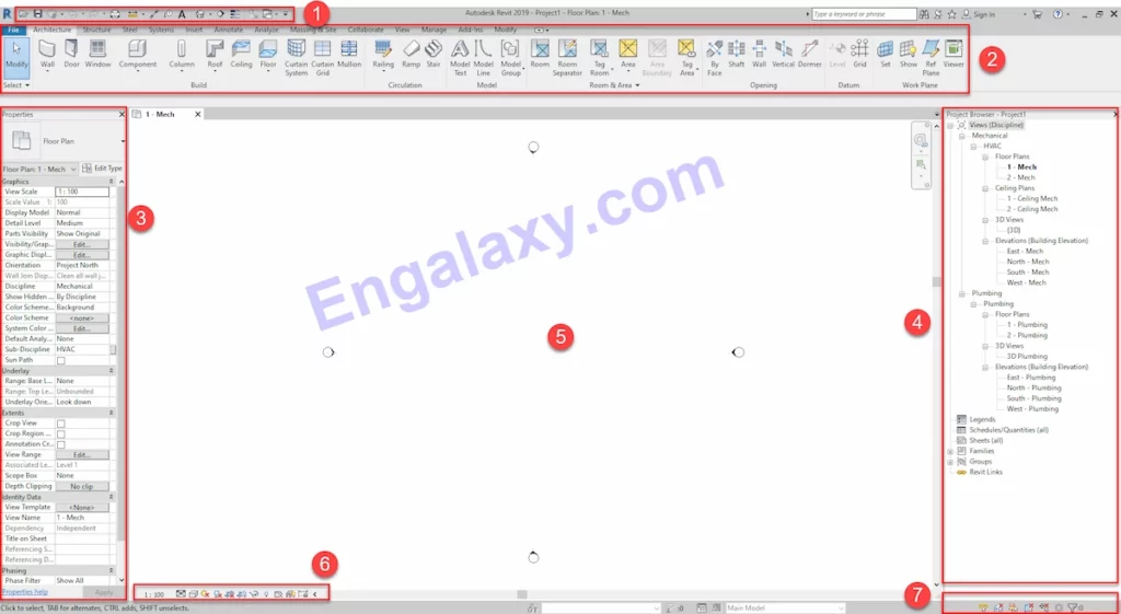
The first one is the Quick Access toolbar.
The second is the ribbon window.
The third one is the properties window.
The fourth one is the project browser.
The fifth one is the workspace, where we will create our model.
The sixth one is the View Control Bar.
The seventh one is this selection toggle.
So, let’s start with the first one, the quick access toolbar.
It will exist at the top of the Revit window on the left side, as seen in the next photo.

It contains different tools, as follows:
- Open: we will use it to open a project, family, annotation, or template file.
- Save: we will use it to save the current project, family, annotation, or template file.
- Synchronize and modify settings: Allows you to specify options for the synchronization process.
- Undo: it cancels the most recent actions.
- Redo: reinstates the most recent action.
- Print: from its name, we will use it to print the files.
- Measure between two references: Measure the distance between two elements or other references.
- Aligned dimensions: places dimensions between parallel references or between multiple points.
- Tag by category: attaches a tag to an element based on the element category.
- Text: adds text annotation (notes) to the current view.
- Default 3D: it opens the default orthographic 3D view.
- Section: creates a section view.
- Thin lines: it displays all lines on the screen as a single width, regardless of zoom level.
- Close inactive windows: it closes open views except for the currently active view, as the current view remains open in the drawing area.
- Switch windows: specifies the view to display or give focus.
Now we will go to the second window, which is the Ribbon window.
Ribbon consists of tabs. Each tab consists of panels.
So the first tab is architecture. It consists of Build, Circulation, Model, Rooms and Area, Opening, Datum, and Work Plane panels, and so on and so forth for all other tabs.
Years before, Autodesk created Rivets for each discipline, Rivet Architecture, Rivet Structure, and Rivet MEP, separated.
Now in new Revit versions, all disciplines are in one software, so some tabs, commands, and features are designed to be used for architecture and structure, like the architecture and structural tabs and some other features.
As our study is related to MEP systems, we will jump to the third tab, the first tab related to MEP services, as you can see in the next photo.

By clicking on the systems tab, we can see sub-disciplines’ panels.
The first panel is the HVAC panel. This panel contains the main tools to create a 3D model for the HVAC system as follows:
- Duct: we use it to draw a duct on the workspace.
- Duct placeholder: it is the same as the duct but draws a single line instead of two lines. It can be used in the design stage to show the routing only. Also, it can be converted to two lines when the sizes are calculated.
- Duct fittings: It places duct fittings in the workspace, such as Elbows, Reducers, Tees, etc.
- Duct accessory: we use it to place duct accessories in the workspace, such as volume control dampers, fire dampers, sound attenuators, etc…
- Convert to a flexible duct: it converts rigid ducts into flexible ducts, but you must have an air terminal connected to the duct.
- Flex duct: it draws round and rectangular flexible ductwork.
- Air terminal: it places a register, grille, or diffuser.
The second panel is the fabrication panel. It contains two tools
- Fabrication part: it displays the MEP fabrication parts palette.
- Multi-point routing: automatically build a run of connected MEP fabrication parts by clicking models in the model.
The third panel is the P&ID Modeler; P&ID is an abbreviation for piping and instrumentation diagrams in this panel.
We can convert the piping and instrumentation diagrams into 3D models automatically.
But first, AutoCAD P&ID. must be available. Usually, It’s used more for water treatment plant stations, power plant stations, and for oil and gas piping.
The next panel is the mechanical equipment panel, to place all mechanical equipment for the HVAC system, plumbing, and firefighting systems, such as fan coil units, chillers pumps, heat exchangers, indoor split units, fans, etc..
The next panel is the plumbing and piping panel.
This panel includes all tools to build the plumbing and firefighting model to draw a pipe in the workspace.
For example, the pipe placeholder is the same as the duct placeholder, as it draws a single line instead of two lines.
Now we can notice a new tool.
We didn’t see it in the duct panel; it’s the Parallel Pipes in the HVAC panel.
To draw parallel pipes for existing pipes, this tool is helpful in the case of two parallel pipes.
For example, the supply and return pipes for the chilled water system, we will use it in the modeling lectures.
The following tool in this panel is the pipe fittings, which place pipe fittings in the workspace, such as elbows, reducers, etc.
But all pipe fittings will be generated automatically in the pipe routing process, so there is no need to use this tool.
The next tool in the plumbing & Piping panel is Pipe Accessories; it places pipe accessories in the workspace, such as isolating valves, strainer, check valves, etc.
Flex Pipe is to draw flex pipes, such as a flex pipe between the network and the plumbing fixture.
The plumbing fixture tool it is used to place plumbing fixtures in the workspace, such as the water closet, sinks, bidet, etc.
And we have here sprinkler to place a sprinkler in the workspace for the firefighting system.
The next panel is the electrical panel. It includes all the tools to create a model for the electrical systems, such as lighting, power, and telecom systems.
The first tool in this panel is the wires. It’s To create a model for the wires between the lighting fixtures, power fixtures, telecom fixtures, etc..
The second tool in this panel is the cable tray, which draws the cable tray into the workspace.
The third tool is the conduit tool, the same as the pipe in the plumbing systems.
The parallel conduits tool is to draw parallel conduits for the existing conduit.
The Cable Tray Fittings tool is to place cable tray fitting in the workspace; it is the same as conduit fittings.
Then we have the electrical equipment tool to place electrical equipment in the workspace, such as the distribution board.
Then we have a device tool to place electrical devices, such as sockets and isolators.
And finally, we have a lightning fixture tool to place lighting fixtures on the ceiling or slabs.
The next panel is the component panel, this is in case a component family is loaded into the project and its category is unknown, so we can use this tool to place it in the workspace.
The next panel is the work plane panel; it makes a specific surface in the model as the work plan to put dimension or draw in it.
We will use this tool in the drawings extraction lectures to put a dimension on the 3D typical equipment details.
That was all in this blog post. In the next blog posts, we will cover the balance items in the Revit user interface.
So, we encourage you to keep following social media accounts to be updated with the coming blog post and updates. You can follow all our social media accounts by clicking this link:
https://link.engalaxy.com/follow-us
Expert Advice
Enroll now in our Full MEP Package of Online Courses and get immediate access to more than 180 lectures in our different online courses. Plus, during your subscription, you will get access to all the new future courses & lectures added to the package.
You can get access to all courses and lectures by clicking this button.
Note: We offer you 14-Day Money Back Guarantee if you don’t like the course
All our blog posts can be found on this link:
Join Our Professional Email List to be notified of New Courses, Free Downloads, Articles…..and much more.
Free MEP English course from this link: