Hi again. Today we will know step by step how to perform Busway Testing & Commissioning on-Site from A to Z.
1- Introduction
1.1- System Description:
A bus duct (also called a Busway) is a sheet metal duct containing either copper or aluminum busbars to conduct a substantial current of electricity. It is an alternative means of conducting electricity to power cables or cable-bus.
1.2- Scope:
The scope of work is to conduct Testing and commissioning for Busway Risers to confirm readiness to be placed safely in service, ensuring the project performance requirement and preserving a log of the testing measurements taken during commissioning for future reference.
1.3- Objective:
The purpose of this method statement is to define the step-by-step procedure to implement the correct practices for the Testing & commissioning of Busway Risers through the guidelines contained here to ensure that the job execution complies with the project specifications and serves the intended function to a satisfactory level.
2- Prerequisites to Procedure
2.1- Site Accessibility and Safety:
- Free access is provided to officially appointed personnel only
- A safe environment is provided in electrical rooms
2.2- Documentation for inspection:
- A method statement is approved, including test forms.
2.3- Quality Control Test reports and submittals:
- WIR for installation is cleared from the major items.
- WIR for testing all the cables connected to the BUSWAY RISER is approved.
2.4- Power on the requirement
- All Electrical Pre-commissioning is to be completed, witnessed, and approved.
3- Design Parameters
- Relevant manufacturer recommendations
- Relevant design and document approvals.
- Relevant materials approvals.
4- Reference Documents/Drawings
4.1- Specification Reference:
- Specification of project 16910
4.2- Relevant Codes / Standards:
- NFPA 70
- NEMA
- SASO
- UL
4.3- Approved Drawing Reference:
- Related approved schematic drawings references are to be attached to WIR & test package
4.4- Approved Schematic Drawing Reference:
- Related approved schematic drawings references are to be attached to WIR & test package.
4.5- Relevant Approved Material Submittal:
- Related approved Material Submittal references are to be attached to WIR & test package.
5- Pre-Start Checks/Pre-commissioning
List all pre-commissioning checks:
The following Checks shall be done for Busway Risers:
A- Ensure that the Busway Riser installation is complete and all electrical & mechanical comments on the installations are completed & approved.
B- Ensure that no damage has occurred between mechanical completion & pre-commissioning.
C- Check that the installation location is free of any water or construction debris.
D- Ensure that the BUSWAY RISER is tagged correctly & identified location-wise and service-wise as specified.
E- Ensure that the wiring termination to the Busway Riser is complete, tight & secure.
F- Ensure that the outgoing cables from the BUSWAY RISER are terminated in the respective equipment panels & adequately tagged and identified.
G- Ensure that the earthing of the Busway Riser is completed.
I- Ensure that the cables to the BUSWAY RISER are correctly tagged & identified.
6- Commissioning/Test Procedures
6.1- Insulation Resistance Test:
· Ensure Isolation of all incoming and outgoing cables.
· Apply a voltage of 500 volts DC between phase ‘R’ to Earth for 1 minute with phases Y, B & N shorted & earthed & record the values.
· Repeat the test for other phases as well.
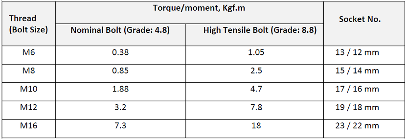
6.2- Busbar Torque Test
· Refer to the table below for the Torque Wrench setting with respect to the hardware size.
· Ensure the proper tightness of the busbar joints with the torque wrench.
· After confirming the correct tightness, apply a red mark on the hardware for indication.
6.3- Commissioning Procedure:
· You need to ensure that all the pre-commissioning checks are carried out successfully.
· The incoming supply of the Busway Riser shall be measured for current, voltage, frequency & phase sequence.
· Check trip operation of circuit breakers (where applicable).
· Check the incomer trip setting.
· Check the circuit breakers on/off function.
· Check the overload relay setting.
· Check timer setting.
7- Interface Procedure
· Permanent power should be provided.
8- Documentation
List all relevant test sheets.
· T&C- BUSWAY RISER Pre-Commissioning Check Sheet.
· T&C- BUSWAY RISER Commissioning Check Sheet.
· Instrument Log.
9- Demonstration Procedures
- After completing the procedures mentioned in section 6.0. The Inspection request with all relevant documents to be sent to Main Contractor for review and inspection.
- After initial verification by the Commissioning Manager, the PMCM will be invited to witness the works.
- After attaining approval, test/report sheets to be signed off from all mentioned in the signature block.
- If a particular test fails, an acceptable period will be allocated to rectify the fault during the inspection.
- Test/report sheets to be distributed as per Project Specifications.
10- Instrumentation
10.1- Personal Protective Equipment:
- Helmet.
- Gloves.
- Goggles.
- Safety Shoes.
- Hi-Vis. Vest.
10.2- Testing Equipment:
10.2.1- Digital Multimeter test tool used to measure two or more electrical values.
10.2.2- Phase Sequence / Rotation Tester
It’s used for detecting the sequence of the supply in three-phase electric circuits.
10.2.3- Clamp Tester
The tool used to measure very high currents
10.2.4- Torque Wrench
A tool that tights the connection bolts to a specific N.m setting
Notes:
· All instruments, testers, and tools will be calibrated and have a calibration certificate not older than 12 months on the test date.
· A Copy of the certificate will be submitted before the test, and it will be available at the site with the device.
11- Staffing
11.1- Testing & Commissioning Engineer
Facilitates all Testing and commissioning of MEP installations of the project, Testing, and commissioning, start-ups, and documentation
11.2- Senior Electrical/Mechanical Engineer:
Controls all the electrical/mechanical installation management processes.
11.3- Safety Engineer:
Responsible for ensuring the safety of the workers and the workplace during Testing and commissioning.
11.4- Commissioning Manager
Verify and approve the testing and commissioning of electrical/mechanical installations and documents before requesting inspections from PMCM/ Client representative.
11.5- PMCMs / Client Representative:
Verify the entire Testing and commissioning of electrical/mechanical installations to witness and approve the test on-site.
11.6- QC Engineer:
Coordinates with the site Engineers and Client Representatives with regards to Testing and commissioning and Hand-over process
Responsible for witnessing the test and will ensure all installation and Testing are approved based on specifications and standards
Should attend during Inspection, Testing & Commissioning, and handover.
11.7- Site Foreman/ Electrician:
To assist with the Testing and commissioning of electrical/mechanical works.
11.8- Supplier’s Representative:
To assess the Testing and commissioning of their owned/supplied electromechanical equipment.
12- Safety Aspects & Permit to Work Requirements
12.1- Health and Safety
12.2- Introduction
. All sub-contractors will comply entirely with JLL approved HSE plan / Ref.
. The contractor must adhere to the JLL health Safety& Environment Policy.
12.3- Safety Aspects & Permit to Work Requirements
· All employees involved in the activity shall undergo a site HSE induction course before the work site.
· Site activities shall be carried out safely according to the approved “Project Health, Safety and Environment Plan.”
· Commissioning team must follow the Client permit-to-work system (Internal) and Client LOTO procedures.
· The commissioning team must read, understand, and follow the JLL / Client LOTO procedures.
· Designated permit issuer/receiver or coordinator shall be appointed to control the commissioning area and commissioning works.
12.4 Training
All commissioning & testing personnel will attend a Safety Commissioning Meeting and pre-commissioning safety training before work commences.
12.5- Hazards Related to Testing & Commissioning
· The following HSE training shall be delivered to the person but not limited to:
- Working at height
- Hazards from electricity
- Use of Power/hand Tools
- Night working.
12.6- Risk Assessment and Control
· HSE Hazards involved in the activity have been assessed through the Hazards & Effects Management Process (HEMP) for every activity, and the outcome is recorded. The contents of the HEMP Register shall be disseminated within the shift supervisor/foreman’s teams through toolbox talks.
· Any new hazards identified other than in the HEMP regarding site conditions shall be assessed, and the Site Engineer/Supervisor shall take control measures before the commencement of any activity.
· The following control measures generally apply to all hazards that shall be adopted as a proactive measure, in addition, the specific controls identified in the HEMP register:
- Correct use & Maintenance of tools and equipment.
- Deployment of a competent personnel for the task.
- Conduct daily toolbox talks before work commencement.
- Good Housekeeping.
- Adequate and effective supervision.
- Provisioning appropriate PPEs based on the nature of the works.
- Awareness about emergency response.
12.7- First Aid / Medical Facility / Emergency Response
· Availability of First Aiders, with ready access to first aid boxes kept at the site, shall be ensured at the worksite.
13- Attachments
- Test Sheets
- T&C- Pre-Commissioning Check Sheet.
- T&C- Commissioning Check Sheet.
- Risk Assessment.
All our method statements are available on this link:
https://engalaxy.com/method-statements