The purpose of this Cable Trays method statement
Organizing Cables can be a hassle, especially if you have a lot of wires and cables. To get a handle on your cables, you need to install a cable tray system. These trays are designed to keep all of your cables and wires organized and contained, making them unobtrusive and easy to navigate.
Cable trays are easy to install, and since they come in different sizes, you can choose the right tray for your individual needs. But to install them properly on-site, you shall have a method statement to be followed to assure everything is installed based on the international codes, and project specifications.
Contents of the installations of Cable Trays Method Statement
1.0 Contractor Details
The works will be undertaken by the subcontractor under the supervision of Main Contractor personnel.
2.0 Scope of Work
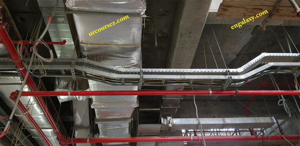
This method statement covers the Installation of Cable Tray, Ladder & Trunking. These installations will be followed as per the Manufacturers recommendation and as per the specifications of the project.
3.0 Programmed Duration of Activity
Works are to commence as per the latest approved schedule.
4.0 Management Structure/Resources and Responsibilities
The overall work will be managed by the MEP Project Manager of the Subcontractor.
Subcontractor teams will control lines and levels of the works. Coring/Excavation will be managed and operated by Main Contractor Plant & Equipment.
The installation will be carried out and managed by using Subcontractor labor.
5.0 Communication/Contact Details
Main Contactor
1-
2-
3-
Subcontractor
1-
2-
3-
6.0 Method Statement
The Installation of Cable Trays will be followed as per the project’s specifications as follows:
6.1. Ensure the installation of cable tray, trunking & cable ladder is carried out in accordance with the manufacturer’s installation recommendations, the requirement of applicable standards, and in accordance with recognized industrial practices and specified in project specification to ensure that installation complies with requirements.
6.2. Prior to starting the installation, refer to the approved shop drawings & coordinated drawings related to the area of installation.
6.3. Mark and line out the route of Cable Tray, Trunking & Cable Ladder as per approved shop drawings & coordinated drawings with marking threads.
6.4. Each run is to be completed before the installation of cables. Submit calculations taking into consideration the maximum load on cable trays with a factor of safety of 300%.
6.5. Remove burrs and sharp edges from cable trays/ladders. Fix trays/ladders using approved suspension rods or steel angle brackets at spacing not exceeding 1.5 m and generally as shown on the Drawings.
6.6. Cables: Secure to tray/ladder with purpose-made straps or saddles and arrange in one layer only, evenly spaced, or as shown on the Drawings, with a minimum spacing of one diameter of the larger of the two adjacent cables or of a trefoil formation of single-core cable circuit.
6.7. Fasten cable tray/ladder supports securely to building structure as specified in Division 16 Section “Basic Electrical Materials and Methods” unless otherwise indicated.
6.7.1. Supports, fastened to the structure, are to carry the greater of the calculated load multiplied by a safety factor of 3. Submit calculations for approval.
6.8. Make connections to equipment with flanged fittings fastened to cable tray/ladder and to equipment. Support cable tray/ladder independently of fittings. Do not carry the weight of the cable tray/ladder on the equipment enclosure.
6.9. Install expansion connectors where the cable tray/ladder crosses a building expansion joint and in cable tray/ladder runs that exceed 27 m. Make changes in direction and elevation using ready-made standard fittings.
6.10. Make cable tray/ladder connections using standard fittings.
6.11. Locate cable tray/ladder above piping, unless accessibility to cable tray/ladder is required or unless otherwise indicated.
6.12. Seal penetrations through fire and smoke barriers according to specification (Through-Penetration Firestop Systems).
6.12.1. Material shall be approved for fire ratings consistent with penetrated barriers.
6.12.2. Material shall be labeled by the manufacturer for fire ratings consistent with a penetrated barrier.
6.12.3. Sleeves: Galvanized steel pipe sleeves. Size as indicated or minimum required size for cable or cable group to be installed provides details.
6.12.4. Sealing fittings: Suitable for sealing cables in sleeves or core drilled holes.
6.13. Sleeves for Future Cables: Install capped sleeves for future cables through fire-stopping sealed cable tray/ladder penetrations of fire and smoke barriers.
6.14. Install cable trays/ladders with sufficient space to permit access for installing cables.
Minimum clearance of 250 mm is to be maintained between the top of tray/ladder and ceiling, beams, and other services, and between tray/ladders in multi-tier formation.
6.15. Barriers: where tray/ladders carry conductors of different systems, such as power, communications, and data processing, or different insulation levels, such as 600V; 5,000V, and 20,000V, use separate cable tray/ladders for cables of each system or insulation class.
In case of absolute necessity, install insulating barriers to separate the systems after obtaining the Engineer’s approval, barriers and spacing between the system’s cables are to be in accordance with relevant codes, standards, and manufacturers’ recommendations.
6.16. Install covers after the installation of the cable is completed.
6.17. Provide labeling for the different cable trays with mentioning these trays are related to which system/service.
7.0 Inspection and Testing
7.1. Test cable trays/ladders to ensure electrical continuity of bonding and grounding connections.
7.2. Do not use metal trays/ladders as an earth continuity conductor. Connect trays/ladders by flexible tinned copper straps to the nearest bare earthing conductor and at maximum 30 m spacing.
7.3. Test pullout resistance for toggle bolts and powder-driven threaded studs for each type and size of anchorage material.
7.4. Replace malfunctioning units and reset until satisfying results are achieved.
8.0 Equipment to be used
• Drill Machine.
• Grinding machine.
• Welding machines.
• Ladder/Scaffolding.
• Hand tools.
• Fork Lift or pallet mover.
• Spirit level.
9.0 Special Scaffold/Access Equipment
Required scaffolding and secured Aluminum ladder for safe passage.
10.0 Training and Competency of Personnel (see also 18 below)
• Civil and Mechanical Engineers.
• Supervisors.
• Foremen.
• Truck Drivers.
• Surveyors.
• General Operatives.
• Firewatcher.
11.0 First Aid and Emergency Arrangements (Including fall arrest, confined space rescue)
A first aid kit is available on site at all times. The site clinic will also be available to provide any necessary treatment.
16.1. AII materials equipment and procedures associated with Fire Production Systems shall be in accordance with NFPA requirements.
16.2. All the materials and equipment received at the site shall be inspected with reference to the approved material submittals.
12.0 Advise Any Permits to Work required (Hot works; confined space; excavation, electrical)
Permit Requirement: Hot Work Permit, Confined Space Entry Certificate, and Permit.
13.0 Environmental Considerations
There is a potential for dust being created during these works, therefore the surface will be periodically treated with water to keep the dust at an acceptable level.
14.0 Waste Management
Housekeeping shall be done on daily basis. Solid waste will be segregated.
15.0 Hazardous Substances – Attach material data sheets
None
16.0 Any Special Storage Requirements
17.0 Testing and Commissioning
Testing and commissioning method statement will be submitted separately.
18.0 Supporting Documents
• Risk Assessments (RA).
• Inspection and Test Plan (ITP).
• Checklist.
If you would like to read more about the other method statements, please visit this link: