The potential for a fire hazard in the workplace is more significant than ever before.
The risk of a fire breaking out due to improper wiring or insufficient sprinkler systems has increased the need for fire suppression.
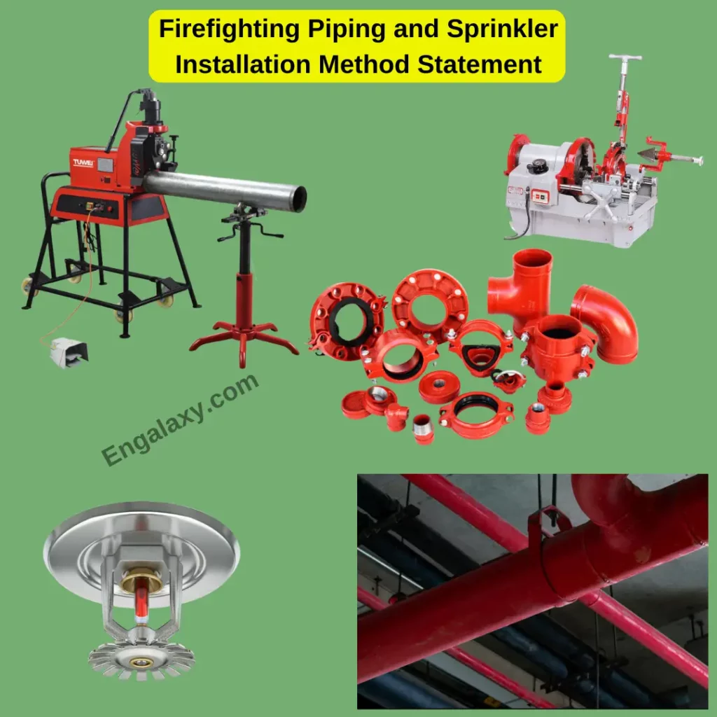
To ensure that your business or facility is adequately protected, it is essential to have the proper piping and sprinkler installation in place.
A well-constructed method statement can ensure that your fire suppression system is properly functioning and meets all relevant safety standards.
In this method statement, we will explore the benefits of a comprehensive firefighting piping and sprinkler installation, the components of a method statement, and the best practices for developing an effective firefighting plan.
By utilizing the latest fire safety technology, businesses can reduce the fire risk starting in the first place and provide an adequate response should a fire occur.
So, In this method statement, we will know how to install the Firefighting Piping and Sprinkler on-site step by step.
01- Contractor Details
Main Contractor will undertake the work.
02- Scope of Work
Scope of work for the Aboveground firefighting system includes installation, testing, and commissioning as per project specifications section 13915 and 13916 fire suppression piping, Section 13975-standpipes and hoses and fire suppression sprinklers standards, respectively, and approved drawings for the satisfaction and approval of the Engineer.
03- Programmed Duration of Activity
On-going for the duration of the building works as per contract.
04- Management Structure/Resources and Responsibilities
The overall work will be supervised by Main Contractor’s MEP Manager Contact details are in section 5 below.
05- Communication/Contact Details:
You can contact us through the following personnel:
Main Contractor Personnel:
Name: Position: Mobile:
Sub-Contractor Personnel:
Name: Position: Mobile:
06- Method Statement/Procedure
06.1- Delivery, Storage, and Handling
All the materials for the system will be used once the PI is done.
Delivery, Storage, and Handling shall be according to the following;
- Ensure that all materials to be used and equipment to be installed should be checked by the Project Engineer/Supervisor against equipment data sheets and approved drawings.
- All materials and equipment shall be inspected by the Quality Control department and approved by the Client/Consultant prior to shifting to the work site.
- Deliver piping with factory-applied end caps. Maintain end caps through shipping, Storage, and handling to prevent pipe end damage and to prevent the entrance of dirt, debris, and moisture.
- Protect stored pipes from moisture and dirt. Elevate above grade. Do not exceed.
- The structural capacity of the floor when stored inside.
- Ensure the valves are dry and internally protected against rust and corrosion.
- Protect valves against damage to threaded ends and flange faces.
- Set valves in the best position for handling. Set valves closed to prevent rattling.
- Do not remove end protectors unless necessary for inspection; then reinstall
For Storage:
- Protect from the weather. Store indoors and maintain temperatures higher than the ambient dew point temperature. Support off the ground or pavement in watertight enclosures when outdoor storage is necessary.
- Protect flanges, fittings, and specialties from moisture and dirt.
- Manufacturer recommendations on handling, repair, laying, jointing, Anchoring, cutting, and other works for pipes and fittings are to be strictly followed. All works shall proceed as per the approved drawings.
- Chemicals such as paint, primer, and thinner must be checked for an expiration date before receiving.
- Storage and handling of Chemicals must be in line with MSDS.
06.2- Fabrication of Joints:
Will be followed as per SECTION 13916:
For Threaded Joints: (pipe size below 2-1/2”)
- The pipe to be threaded is cut based on the approved shop drawings.
- Threading of pipe is carried out by means of a threading machine (taper threaded).
- The threading machine will be inspected daily before starting the work.
- The surface of the pipe to be threaded is cleaned.
- Any internal burrs from the pipe are to be removed to restore the full inside diameter.
- Teflon materials or Teflon tape are wrapped over the threaded position before making the pipe joint.
- Required fitting is tightened over the threaded portion either before installation or in position.
- Exposed ends of pipes are capped to prevent debris and other materials from entering the pipe.
- All measured pipes should be free from stress & strain at threaded /flanged joints.
- Unions are to be provided wherever necessary for the easy removal of pipes, valves & fittings.
- Where the pipes of dissimilar materials are to be joined together, necessary dielectric unions shall be used.
6.3- For Grooved /Coupling Joints: (Pipe size 2-1/2” & above)
Will be followed as per SECTION 13916 PART 2.6:
- Utilization of the grooved piping method is based on the proper preparation of a groove in the pipe end to receive the key.
- The groove serves as a recess in the pipe with ample depth for secure engagement of the coupling yet with ample wall thickness for full pressure rating.
- The grooving tools mount directly to the power source with support legs. A manual hydraulic pump provides force for the grooving.
- A micrometer-type dial provides an easy setting of groove dimension stop. Rigid groove end piping systems provide a mechanical and frictional interlock onto the pipe ends sufficient to result in a rigid joint.
- Remove dirt, scale, and foreign matter from inside and outside pipe surfaces.
- Pipe ends must be cut square. All internal or external weld beads flash, or seams must be ground flush at least 2 inches back from the pipe end.
- The pipe is properly supported with a pipe stand, and it should be located ¾ of the pipe length from the grooving machine.
- Raise the upper groove roll housing and open the groove roll from the drive roll by turning the depth adjustment screw.
- Raise the feed handle and place the pump release lever in the return position. Rotate depth adjustment by approx. one revolution. Press the footswitch to start the machine and apply a steady pressure to feed the hydraulic pump handle.
- Continue applying steady pressure until groove depth is reached. Allow one full revolution before increasing pressure on the rolls to prevent overload. Further grooves with the same pipe will be made to the same depth.
- Exposed ends of pipes are capped to prevent debris and other materials from entering the pipe.
6.4- Method of Installation:
Will be followed as per SECTION 13916/NFPA -13:
Installation of Horizontal Run
- Mark the route of piping on the soffit of the slab by following the approved shop drawings, combined service drawings, and site coordination with other services based on the given and final reference points.
- Install approved anchor fastener as per project specification, approved material submittal, and approved shop drawings.
- All pipe supports shall be done as per approved drawings regarding size/spacing and manufacturer recommendation, and ensure all fixings (threaded rods, angles, clamps, etc.) are straight and secure.
- Any cut edges of angles, channels, or threaded rods will be painted with touch-up or zinc-rich paint. Adequate supports are to be provided before and after valve fittings, flexible joints bend off-sets, etc.
- The pipework shall be supported, anchored, and guided to preclude failure or deformation. Supports shall be designed to support the weight of the pipe and the weight of the fluid.
- Piping shall be securely fastened to the structure without over-stressing any portion of the structure itself. Pipe supports, anchors, and guides shall be secured to concrete by means of inserts or, if greater load-carrying capacity is required by means of steel fishplates embedded in the concrete.
- Hangers shall be arranged so as to prevent transmission of vibration from piping to building or support.
- Pipe hangers and supports shall be furnished, complete with rods, bolts, locks, nuts, and other components and accessories to allow installation to expand freely and contract.
- Hanger spacing shall be such that piping is installed without undue stress and strains, and provision shall be made for expansion and contraction, structural settlement, and water hammer.
- Supports, clamps, and hangers shall be made of galvanized steel and fixed with drilled plugs.
- Sleeve passing through partition walls and floors. Make sure the pipe is in the center of the sleeve by fixing the spacer.
- Pipe passing through the sleeve shall have enough space of at least 50mm for the application of fire stop.
- Minimum clearance between pipe & structural must be maintained, and pipe supports spacing must be as per the approved shop drawing. Place hangers within 300mm of each horizontal fitting.
- All pipes should be cleaned internally during construction and installation. Open ends shall be plugged in properly. Pipes shall be protected during the remainder of the project.
- Provide clearance for access to valves.
- Expansion/Contraction joints will be provided wherever applicable as per approved drawings.
06.5- Installation of Vertical Risers.
Will be followed as per SECTION 13916-13975:
- Mark the pipe routing on the risers/shaft as per the approved drawing.
- Piping shall generally be run parallel to walls and beams. Coordinate with other trades before finalizing the location of any piping to avoid interference with work.
- Support vertical piping on each floor. Support riser piping independently of connected horizontal piping.
- The sleeves/opening should be straight in line throughout the shafts to avoid any off-sets, which in turn reduces the number of fittings used, thus reducing friction loss.
- Pipes passing through sleeves shall have enough space of at least 50mm for the application of fire stop.
- Pipes are installed in position by suitable lifting equipment.
- Furnish and install all drain piping, flushing, connections, drain plugs, etc., at drain points and all low levels.
- Seal all valves not provided with tamper switches in the open position by approved means. The flushing connection shall be as per NFPA 13.
- Only concentric reducer fittings will be used for riser pipes.
- Ensure proper platforms are made for safe working inside the shaft and that all PPE is available.
06.6- Sprinkler System Alarm Devices:
Will be followed as per SECTION 13916:
- The system shall be provided with alarm devices consisting of but not limited to items described for the following devices:
- Installation of Sprinkler Heads will be based on manufacturer instructions, and automatic sprinklers are as follows;
- Concealed pendent for installation in a false ceiling to provide an aesthetically pleasing appearance and to have a 15mm orifice.
- Exposed installation, brass finish, upright type of high-quality bronze construction, and to have 15mm orifice.
- Concealed sidewall type of high-quality bronze construction and has 15mm orifice.
- Pendant, chrome plated semi-recessed and to have 15mm orifice.
- Upright exposed and side wall exposed with the brass finish of high-quality bronze material and standard 15mm orifice.
- Automatic sprinklers to be fusible link type.
- The sprinklers and pipelines shall be located and spaced based on approved drawings.
- Fix the sprinkler floor control valve as per the approved shop drawing. Ensure that valves are located at an accessible location.
- Installation of sprinkler heads will be done after pipework flushing is completed.
06.7- Flushing of Piping:
- Flushing of the system will be after the successful completion of the pressure testing.
- Firefighting piping, from the water supply to the system riser and leading connections to the system riser, shall be completely flushed before the connection is made to downstream fire protection system piping.
- The flushing operation shall be continued for a sufficient time to ensure that the pipes are clear of debris and other residual material.
- The minimum rate of flow shall be not less than one of the following:
- Hydraulically calculated water demand flow rate of the system, including any hose requirements.
- Flow necessary to provide a velocity of 10 ft/sec (3.1 m/sec) in accordance with NFPA.
- Maximum flow rate available to the system under fire conditions
| Table 10.10.2.1.3 (from NFPA) Flow Required to Produce a Velocity of 10 ft./sec (3m/sec) in Pipes | ||||
| Pipe Size | Flow Rate | |||
| in. | mm | gpm | L/min | |
| 4 | 102 | 390 | 1,476 | |
| 6 | 152 | 880 | 3,331 | |
| 8 | 203 | 1,560 | 5,905 | |
| 10 | 254 | 2,440 | 9,235 | |
| 12 | 305 | 3,520 | 13,323 | |
06.8- Hydrostatic Testing;
The test shall be carried out as per the following procedure;
- Make available a highlighted drawing of the area intended for hydrostatic testing. Indicate on the drawing the location of vent/drain valves, plugged connections, and water pressure pump connection.
- As per NFPA 13 & NFPA 24, all piping and attached appurtenances subjected to system working pressure shall be hydrostatically tested at 1.5 times working pressure for 24 hours.
- Pressure loss shall be determined by a drop in gauge pressure or visual leakage.
- The test pressure shall be read from one of the following, located at the lowest elevation of the system or the portion of the system being tested:
- A gauge is located at one of the hydrant outlets.
- A gauge is located at the lowest point where no hydrants are provided.
- Fit threaded end plugs secured to resist the full hydrostatic pressure at the lower end of the pipe network and Pressure gauge as necessary.
- The hydrostatic test shall implement the use of two nos. of pressure gauges, one at the highest point and one at the lowest point of the tested pipeline.
- Connect the pump to the lower end of the piping network.
- Fill the pipe with water until all air is removed from the piping network and respective pressure is reached in the piping network as per specification and manufacturer recommendation.
- Invite the Engineer to note the pressure and again witness the pressure after 2 hours.
- Repair any leaks found and arrange a retest.
- Make a report for the test with a diagram indicating the area tested.
- Replace piping system components that do not pass test procedures and retest to demonstrate compliance. Repeat the procedure until satisfactory results are obtained.
- Report test results promptly and in writing to Engineer and authorities having Jurisdiction.
07- Inspection and Test Plan (Quality Records)
See reference ITP in Section 18
08- Tools and Equipment
- Oxy/Acetylene Welding Machine
- Chain blocks and lifting equipment
- Grooving Machine
- Threading Machine
- Hack Saw/Tube Cutter
- Electric Drill with 4” & 6” Grinder
- Pressure gauges (Calibrated with report)
- Manifold (Calibrated with report)
- Manual pump
- Hoses
- Level bar
- Measuring Tape
- Ball hammer and cold chisel
- Pressure Gage (0- 250 psi)
09- Special Scaffold/Access Equipment
Normal Scaffolding will be required up to the standpipe level.
10- Training and Competency of Personnel
Installers, Pipefitters, and fabricators shall be well-trained and experienced.
11- First Aid and Emergency Arrangement
The site team will have a first aid kit available at the time of work, and the site clinic is also operational as necessary.
12- Advise Any Permits to Work required
- Electrical small hand tools permit.
- Hot work permit
- Cold work permit
- Excavation permit
- Confined space permit
13- Environmental Considerations
Wastewater from flushing and disinfection will be disposed of in the proper way as per ADA regulations.
14- Waste Management
The site has Waste Management Plan that covers all Construction waste.
15- Hazardous Substances – Attach material data sheets
None
16- Special Storage Requirements
None
- Testing and Commissioning:
After successful installation, Inspection Request will be raised.
18- Supporting Documents:
- Risk Assessment (RA)
- Inspection and test plan (ITP)
- Checklist
Please click on the next button if you want the complete editable file ( Word File )of this method statement and other method statements.
Also, If you would like to learn the different Mechanical practical installations on-site, you can have a look at our Mechanical Practical Installations Online course from this link:
Also, you can find all our published method statements on this link:
https://engalaxy.com/method-statements/
If You would like to learn more about the practical installations of the different MEP systems on-site, so have a look at our free MEP Mini-Course