SOP for Air Handling Unit or Sequence of Operation for AHU
The Air Handling Unit or AHU is the heart of an HVAC system, and it is responsible for handling air, as well as removing heat and moisture from the ductwork and forcing it into the HVAC system.
The AHU is the heart of the entire system, so today in this post, we will see together the SOP for Air Handling Unit or AHU, whose type is constant Air Volume.
Air Handling Unit / AHU components
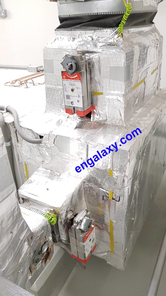
The AHU supply unit consists of an intake section, panel, and bag filters, a mixing damper section, chilled water supplied cooling, and a supply fan. The AHU extract unit consists of an exhaust fan section.
I. Normal Mode of Operation
A. Start-up, Fan Operation, and Damper Operation
The AHU Supply Fan and its corresponding Return/Exhaust Fan will be started and stopped remotely from the BMS via operator command or automatically via a time-scheduled program from the BMS Workstation.
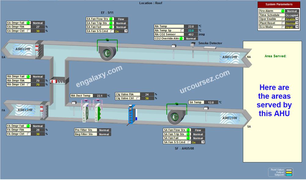
Once the AHU is operational, the Exhaust and Fresh Air Damper will open at 30% (adjustable) and the Return Air Damper at 70% opening (adjustable).
An airflow switch will be installed across the Supply Fan and Return/Exhaust Fan to monitor its On/Off Status.
A no airflow alarm will be activated through the DDC software program whenever the Supply Fan and Return/Exhaust Fan fail to run (i.e., broken fan belt).
Once the no airflow alarm is rectified, a software parameter reset is available in the BMS.
Once activated by the BMS Operator, the Supply Fan and Return/Exhaust Fan will automatically restart to their normal operating condition.
Whenever the AHU and Return/Exhaust Fan are stopped, the software program interlocked Motorized Fresh Air Damper and Exhaust Air Damper will close, and the Return Air Damper will open at 100% opening.
The AHU Fan and Return/Exhaust Fan will operate independently of enabled signals. The Time Schedules for both fans shall be set as the same initially.
They shall also be given a time delay on start-up to enable the fans to establish a run condition (AHU Supply Fan first, then Return/Exhaust Fan).
B. Temperature Control
Whenever the AHU runs, the airflow switch across the supply fan will enable the DDC temperature control, and the Return air duct temperature sensor through the DDC software program will control the cooling coil 2-way valve to maintain the required return air temperature setpoint of 22 deg. C (adjustable via the BMS Workstation).
If the return air temperature is above the setpoint, the DDC will modulate the cooling coil 2-way valve to open until the setpoint is attained, and when the return air temperature drops below the setpoint, the DDC will modulate the cooling coil 2-way valve to close and sequence the Electric Duct Heaters until the setpoint is attained.
Refer to Electric Heater Battery sequence of operation. Once the AHU ceases operation, the cooling coil 2-way valve will automatically close.
C. Fresh Air, Exhaust Air, and Return Air Motorized Damper Economizer Control
The common Return air duct temperature sensor of the AHU will be monitored by the BMS to control the Fresh Air, Exhaust Air, and Return Air motorized damper in sequence for economizer control.
Whenever the return air temperature is above the outside air temperature, the fresh air and exhaust air will be modulated to open (100%), and the return air damper will be modulated to close (0%) to allow more fresh air intake.
And whenever the return air temperature is below the outside air temperature, the fresh air and exhaust air will be modulated (30%), and the return air damper will be modulated to (70%) to allow more return air intake. The fresh air damper is modulated to a minimum (30%) position to ensure a minimum fresh air intake.
D. Air Quality Monitoring
The Return Air Carbon Monoxide sensor of the AHU will be monitored by the BMS to control the Fresh Air, Exhaust Air, and Return Air motorized damper in sequence to satisfy the Air Quality within the supplied area.
Whenever the CO2 sensor is above the required set-point (750ppm) cut-in, the Damper Economizer Control will be overridden, the Fresh Air and Exhaust Air Damper will be modulated to (100%), and the Return Air Damper will be modulated to (0%) to allow more fresh air intake.
The Damper Economizer Control will automatically restart its normal operating sequence when the CO2 sensor is in normal condition (650ppm) cut-out.
E. Fire Alarm Signal
A Fire Alarm Signal is monitored by the BMS. Once it is in alarm, the DDC will automatically shut down the AHU, and at the same time Exhaust Air, Fresh air Damper will be closed (0%), and Return Air Damper will open (100%). Once the fire alarm is rectified, the AHU will automatically restart its normal operating condition.
F. Interface with Fireman’s Panel with Override Switch
OFF Mode: All Air Handling units (AHU) and Exhaust fans (EF) located within the Building will be turned OFF. Exhaust & Fresh Air Damper will be Closed, Return Air Damper will be opened.
AUTO Mode: All Air Handling units (AHU) and Exhaust Fan (EF) located within the Building will be in NORMAL operation and will be controlled thru BMS.
EXTRACT Mode: All Air Handling Unit (AHU) will be turned OFF, and Exhaust Fan (EF) will be turned ON. Exhaust Air Damper will be Opened, Return Air Damper will be closed, and Fresh Air Damper will be closed
ON or PURGE Mode: All Air Handling Unit (AHU) and Exhaust Fan (EF) located within the Building will be turned ON. Exhaust Air & Fresh Air Damper will be Open, Return Air Damper will be closed.
II. BMS Monitoring & Controlling
- Supply / Mix / Return Air Temperatures
- Supply Fan/Exhaust Fan Airflow Status
- Supply Fan/Exhaust Fan Motor Start/Stop Command.
- Cooling Coil Valve Control Signal Output & Actual Feedback.
- Dirty Filter Alarm (Pre-Filter and Final Filter).
- Fresh Air Motorized Damper Control Signal Output & Actual Feedback.
- Exhaust Air Motorized Damper Control Signal Output & Actual Feedback.
- Return Air Motorized Damper Control Signal Output & Actual Feedback.
- CO2 Sensor
- Fire Alarm Signal
- Electric Heater Battery(EHB) Control (0-100%)
Conclusion:
In summary, the Air Handling Unit is a key component of HVAC. It is the main atmospheric control equipment that is intended to deliver air to the occupied spaces of a building or structure.
The AHU is composed of a variety of devices, including air intakes, heat exchangers, fans, dampers, motors, compressors, filters, and vents. The AHU can be located outdoors or indoors, depending on the requirement.
If you would like to learn in detail about the Building Management System or BMS, click on the next button to grab the limited-time offer to the BMS course with lifetime access.