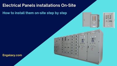
Electrical Panels is mandatory to be found in all kind of projects. This is to feed all the electrical loads with the required power.
In this article, I’m focusing on the practical installations of these electrical panels On-Site.
First of all, let us know the different types of panels which you can find in your project.
Types/names of the electrical panels:
01- Ring Main Unit Panel, will be used with the Medium Voltage System (MV).
02- Switchgear Panel, also like the above panel, will be used with the Medium Voltage System (MV).
03- Outdoor Package Substation, this is a combined unit which will include different items, RMU on the MV side, in the middle will be a step-down transformer to convert from Medium Voltage to a Low Voltage, and the last part of this panel will include the LV side “MDB panel”.
04- Main Distribution Board, or MDB.
05- Synchronization Panel for the Generators.
06- Automatic Transfer Switch Panel, or ATS panel.
07- Manual Transfer Switch Panel, or MTS panel.
08- Uninterruptible Power Supply panel, or UPS panel.
09- Motorized Control Center Panel, or MCC panel.
10- Control Panels
11- Sub-Main Distribution Panel, or SMDB.
12- Final Distribution Panel, or FD panel.
13- Lighting Control Panel, or LCP.
14-…..other panels.
Now, you will know how to install practically on-site the SMDB, or Sub-Main Distribution Boards, plus the Final Distribution Boards.
Firstly, the installation works of the electrical panels shall be carried out only in accordance with the latest approved shop drawings, approved material submittals, and the project specifications.
Secondly, here is a list of the tools which will be required to complete the job:
Thirdly, these are the step of the installations:
Please make sure that all the civil and finishing activities are completed before starting the work.
Ensure the area is released for the area of installation and cleared by the civil section to1 proceed with the Distribution Board installations.
Also, ensure that the work area is clean and safe to undertake activities.
Ensure the floor/ wall surface is ready to install the Distribution Boards.
Clearances are to be maintained between the SMDB’s and FDB’s, as specified in the approved shop drawings.
The height of the Distribution Boards shall be maintained as per approved shop drawings so that easy access for termination of cables and other maintenance works can be carried out.
Connection of cable trays / Cable trunking with all Distribution Boards shall be done rigidly with proper supports.
All knockouts made on the panel covers shall be filed and provided with grommets to avoid sharp edges and unused knockouts shall be covered.
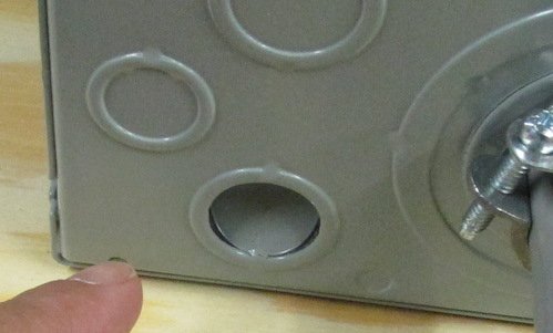
All cable entries shall be closed and sealed in a proper way.

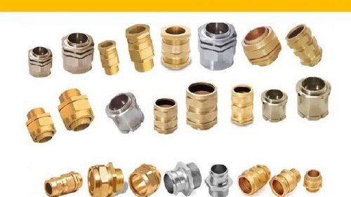
Termination of cables shall be done using approved cable glands, lugs.
Connections should be done by only competent technicians electricians as per the approved shop drawing.
SMDB’s and FDB’s shall be provided with proper earthing connections as per approved shop drawings.
Approved Heat Shrinks to be installed above each lug inside the panel.
This is a sample of the heat shrink
This is a sample of the Cable Lugs
Doors of SMDB’s and FDB’s are to be earthed with flexible connections.
Identification labels of approved type shall be fixed on SMDB’s and FDB’s.
Raise (WIR) for installation of SMDB’s and FDB’s along with glands installations and termination to Consultant.
You can watch this video to show you the different components of SMDB practically on site.
(Free videos) The practical explanation for the components of the electrical panel On-Site
Please make sure before starting the works, that your electrical team are wearing their proper PPE, if you would like to know more about the most important PPE, click here
Also, if you would like to know more about the tools to be available with the electricians, click here