
A relay plays an important role in controlling and monitoring the various components of a building management system.
It acts as a switch that transmits signals from one component to another.
With a relay, building maintenance staff can easily monitor and control HVAC, lighting, and security systems from a central location.
However, the relay in building management systems is not a one-size-fits-all solution. Different relays may be required depending on the type of building and its unique needs.
Therefore, building owners and managers must work with experts in the field to identify the right relay solution for their buildings.
In this blog post, we will delve deeper into the role of relays in building management systems.
An automation relay is an electrical switching device that can be controlled using an electrical control signal.
This electrical control signal can be supplied using any controller, such as PLCs in industrial automation or DDCs in our building automation.
Or this control signal can be supplied by a selector switch, as you see in the MCC panels.
Before discussing further, let’s look at an application of Relay.
Here is a simple light bulb circuit where a manual switch is used to control the on-off operation of the bulb as we do in our homes.
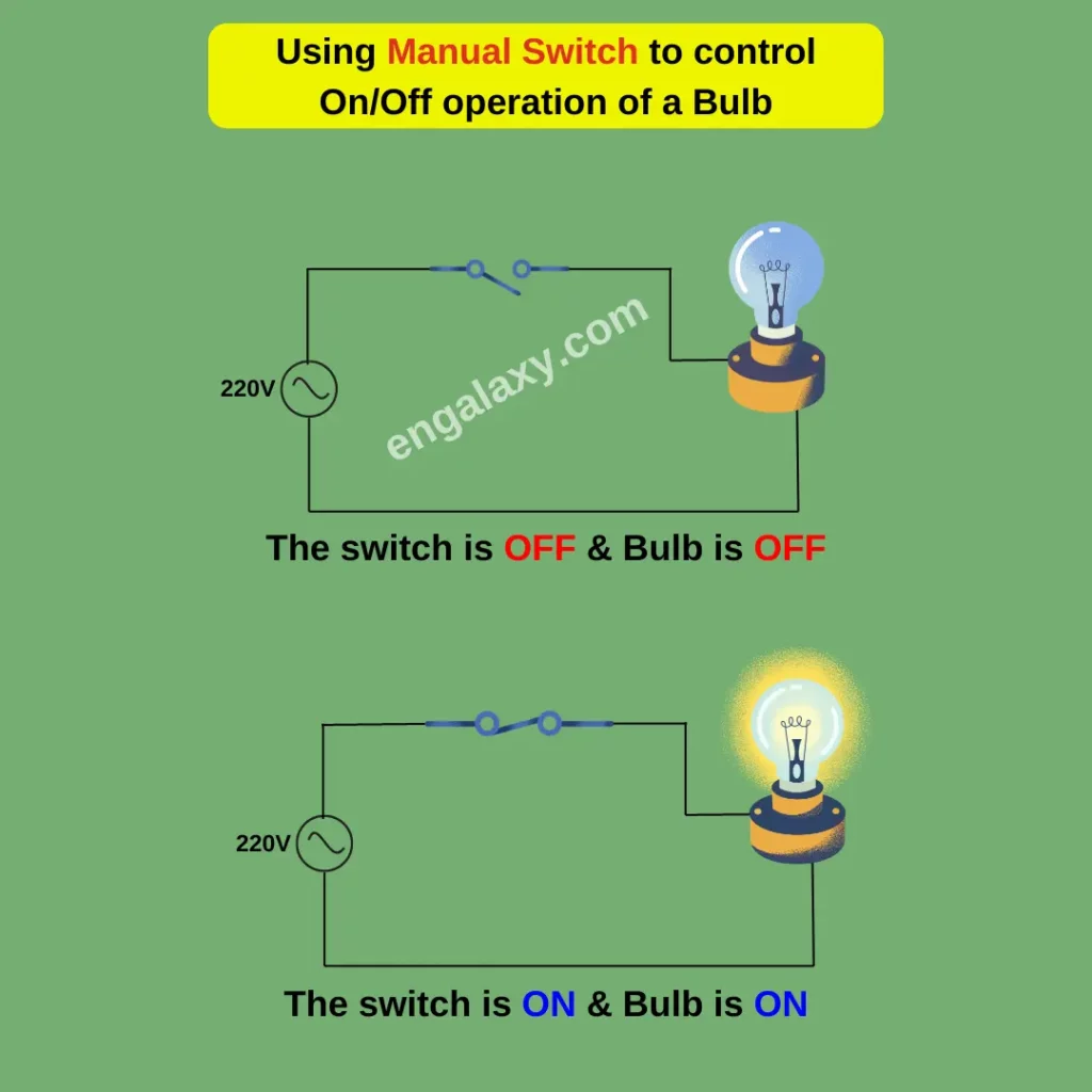
Now, how can we perform this task if we have to control the same circuit using a control signal from some type of controller without the need to use a manual switch?
Yes, you are right.
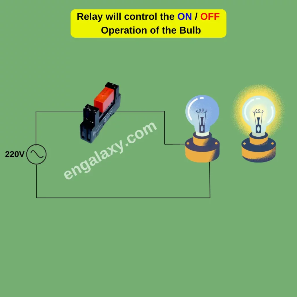
We can use a relay to achieve our goal.
To turn on or off the bulb, a relay is controlled by a signal that energizes or de-energizes it.
Now let’s see how a relay works.
There are different types of relays.
But electromagnetic relays are the most common type of Relays you will see in MCC and DDC panels and industrial automation.
Here is a symbolic representation of a relay.
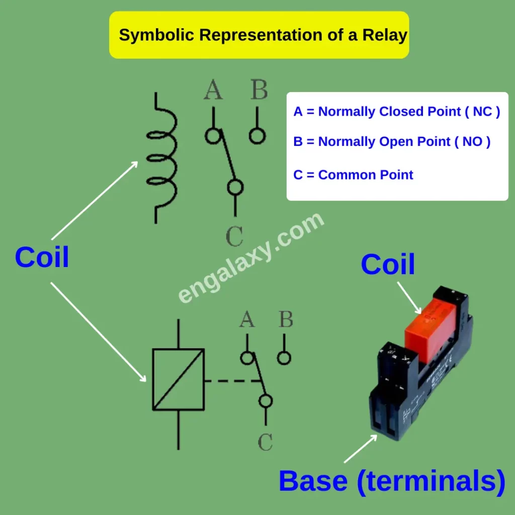
It consists of different parts, but two of them are the most important.
First is an electromagnetic coil, which is used to make electromagnetic when a voltage signal is applied to this coil.
The second part is the metallic contacts.
These contacts are used for switching purposes.
Let me explain further about these parts.
Here, we have three contacts.
One is common ( C ), the other is NC or normally closed ( A ), and the third is normally open ( B ).
First of all, common is the contact where we will apply our voltage.
For example, if we want to apply 220V to a bulb, then we will supply our 220V on this common part.
Okay.
And then NC is the contact, which would be normally closed.

Normally closed means when the Relay is de-energized, or there is no control signal applied on our Relay, then this common point would be connected to this NC point, and NO means normally open.
Normally, this point is open. As you can see here, it’s open.
But when the Relay is energized, and a control signal is applied, this movable part of the contacts will move and come to the NO point.
Here is another relay representation showing a coil and the contact parts.
As you can see, the Relay is de-energized, and our common point is connected to the NC point.
When the voltage is applied to the relay coil, the Current flowing through the coil makes an electromagnetic field, which pulls the movable common contact and connects it with the NO contact.
As you can see here, now our common point is now connected with the NO instead of the NC point, which was our case earlier.
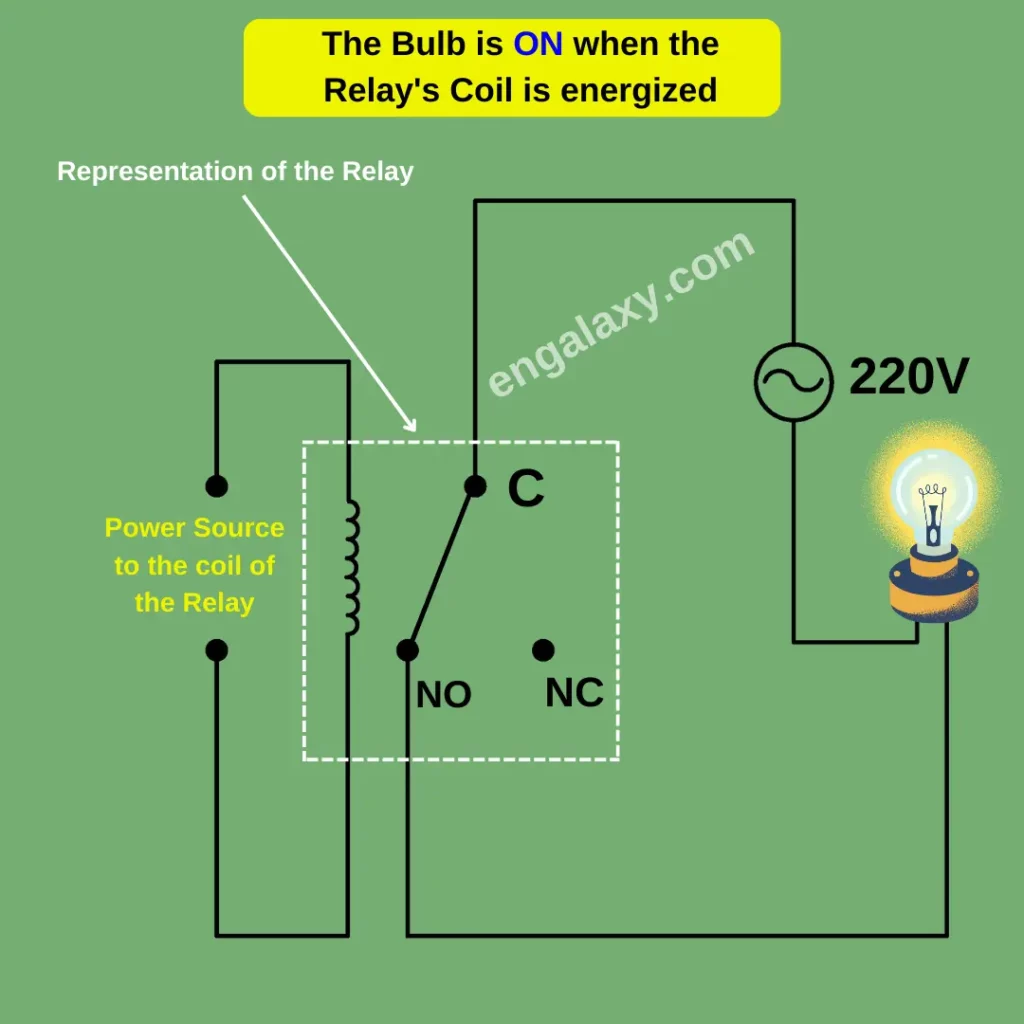
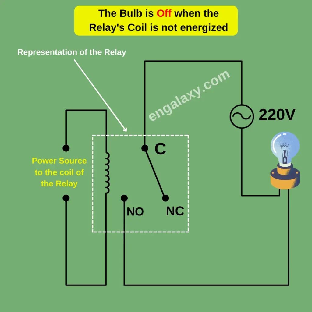
Now let’s have a look at a simple application of a relay where we can use this Relay to switch a light bulb.
The circuit shown here will be used for this purpose.
Let me explain it further.
First of all, we have this coil, and no voltage is applied to this coil.
We shall apply a control voltage on this coil to energize the Relay.
Then, we have a voltage source that will be used to energize the light bulb.
As you can see, one side of this source is directly connected to the bulb.
This is a neutral side, or it can be a line side.
The second side is connected to the common of the Relay.
And the other side of the bulb is now connected to the NO point.
In this case, when Relay is de-energized, the common point is directly connected to NC, not the NO point.
So the circuit is not completed.
Now, as the control voltage is applied to the Relay, the Relay is latched, and our circuit gets completed.
Now, the common is directly connected to the NO point.
Now, on this bulb, we have a line on one side, and on the other side, we have neutral.
So the circuit is complete, and current starts flowing through the bulb, lighting it up.
In the same way, we can use Relay for different applications. Like, we can use this Relay to switch off our damper actuators and valve actuators or to give a command to our fan motors.
So, the concept of the relay wiring would be the same irrespective of our load.
An electromagnetic relay consists of two major parts.
First is a base, which is fitted on the din rail inside the panel, and wires are connected to this base.
The other part consists of coil contacts and other parts.
This part is fitted on the base.
There are pins on the coil part, which are then inserted into the base so it is pluggable.
Even if our coil part is damaged, we don’t need to replace the base; we can just replace our coil part.
The base shown here is for a 14-pin relay.
Let’s see how we can make wiring for this Relay.
On each terminal number, you can see two numbers are mentioned.
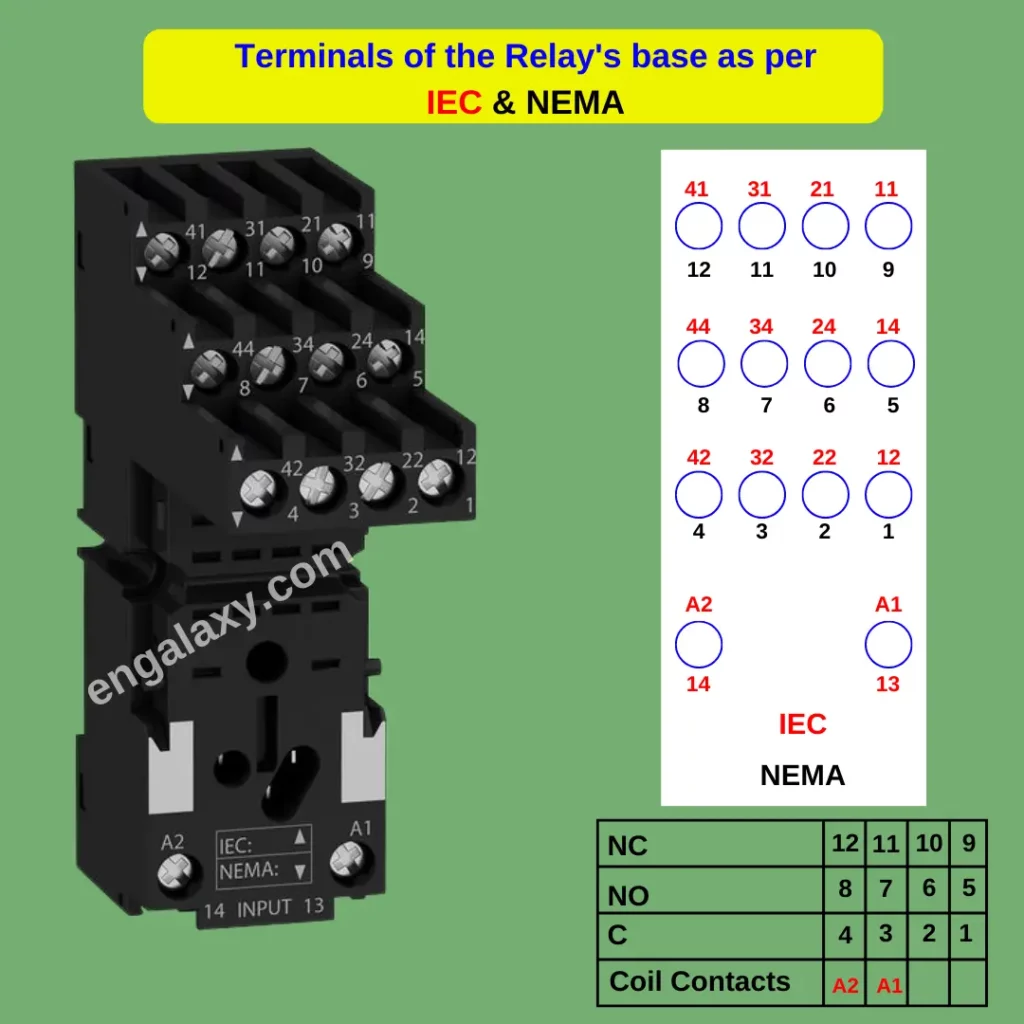
One number is per the IEC standard, and the other is per NEMA.
So you can see here IEC and NEMA.
And there are two numbers mentioned, which I explained here.
So it’s easier to refer to this drawing.
So as you can see here, as per NEMA, the numbers are in black, and as per IEC, the numbers are in red.
So you will see a schematic on the relay coil part showing how to make your Relay wiring.
I will explain it here to make it easier for you to understand later.
First of all, we have A1 and A2 terminals.
Here, we will apply our control signal, which will energize our Relay.
Then remaining, we have 12 contacts.
Okay.
As we saw earlier, for each switch, we have three contacts.
One is common, and the other is normally open or NO, and the third is normally close or NC.
So here we have four switches, one, two, three, and four, each having a three-contact.
So, in total, we have 12 contacts or 12 pins for the switch; the other two are for the control signal.
So, first of all, we have a common point.
Here, we will apply our common signal if we want to use this switch.
And then, as we can see here, this one part, this one is normally close, so this is NC contact, and the other five are NO.
So, if we want to use NO for this switch, we will apply our voltage signal on this point, and then we will connect our wire to the number five terminal.
So, similarly, you can use the other three relay switches and make wiring for those.
We will connect our voltage signal on the common, and then on the other side, we will connect to our Normally open (NO) point, or if, in some applications, you want to connect on the NC point. It can also be done.
Now, let’s see how to select a relay.
Many factors can affect the relay selection, like the number of required switching contacts, but we will look into the most important parameter, which is the coil voltage rating.
The relay coil can be either AC or DC.
And the second parameter is the voltage level.
First, we shall know that our control signal is AC or DC, so we shall select the coil accordingly.
And what is the voltage level of our control signal?
Is it 24-volt ac, 220-volt AC, 12-volt DC, or 24-volt DC?
The second thing is contact voltage rating.
It is also a very important factor.
Because some of our loads would be working on 24-volt AC, like some of our damper actuators or valve actuators would work on 24-volt AC, but some other loads would work on 220-volt AC.
So, our contact switches must be compatible with that voltage level.
So, you must see this parameter while selecting a relay.
This is mentioned on the Relay itself, like the coil voltage rating.
The third point is the contact’s current rating.
It is also very important how much ampere our load is going to take if our load is going to take one ampere, we can select a one-ampere relay.
But if our load is two amperes, we cannot use a one-ampere relay for that load.
You should take into account all these points while selecting or purchasing a relay for your application.
Now, let’s have a look at the application of relays in the BMS system briefly.
First of all, you will see relays inside the DDC panel.
They are used as a buffer between the IO modules and the field devices for commands.
Buffer means that even your IO module will have relays inside, but you can use them between the IO module and your field devices.
So in case there is any issue with the field devices, your relay module would be safe.
And also, if our control panel is out of service, we can manually give commands to those loads using a latching switch on the Relay itself.
Also, if the rating of the relay module does not match the load requirement, for example, if our relay module supports only 24-volt AC and our load is 220-volt AC, then we can use a relay between them.
So, usually, inside the DDC panels, relays can be used for command of our actuators, damper actuators, valve actuators, and fans.
You will also see relays inside MCC panels, as they can be part of the control circuit there.
Also, they are used there to provide monitoring signals for motor runs and trip status.
Here I have a picture of a panel where you can see that the relays are mounted on the din rail, and they are wired.
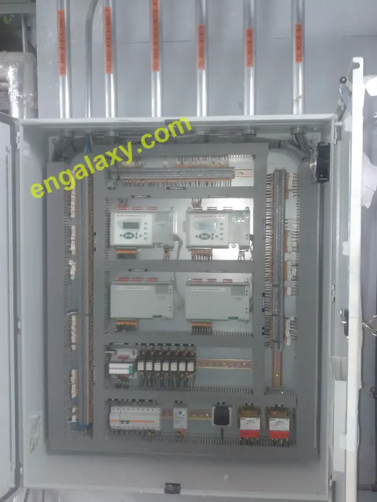
So this is how you will see relays inside your panels.
All our blog posts can be found on this link: